
Owner manual

CHAPTER 2 - SPECIFICATIONS
2-3
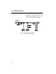
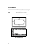
Connectors Phoenix Combicon type with unsealed screw
terminal mate. PC board side-vertical pins.
All connector numbering is from left to right
when looking down on the board with the
connector side of the board facing toward
you.
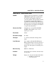
J1 Load Sensor 8 Pin
8 + EXC (Plus Excitation) + 5VDC
7 + SEN (Plus Sense)
6 + SIG (Plus Signal)
5 - SIG (Minus Signal)
4 - SEN (Minus Sense)
3 - EXC (Minus Excitation)
2 + C2
1 - C2
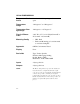
J2 DeviceNet Interface 5 pin Open
1V - (Black)
2 CAN- (Blue)
3 SHIELD (Bare)
4 CAN+ (White)
5V+ (Red)
J3 Set Point Out Interface 4 Pin
1 RLY 1 (Set Point Output One)
2 GND (Ground)
3 RLY 2 (Set Point Output Two)
4 +5 VDC