
Instruction Manual


Chapter 2 - Installation
2-1
CHAPTER 2 - INSTALLATION
Remote I/O Board Cable
Termination Dip Switch
Configuration
About Cable
Termination
Weight controllers are connected to a cable in daisy-chain fashion and
are referred to as “nodes”. A Daisy Chain is a hardware configuration
in which devices are connected one to another in a series. The end
nodes on the daisy chain require termination resistors. The Remote I/O
board provides the S1 Dip Switches which are used for cable termina-
tion based on the baud rate. (See Table 2-1) The S1 Dip Switches are
only used on the last device in the daisy chain. For all other devices on
the daisy chain both dip switches should be set to OFF. (See Fig. 2)
NOTE: Refer to your Allen-Bradley PLC-2, PLC-3, PLC-5 and SLC 500 manuals for the
maximum number of nodes available.
Setting the Cable
Termination Dip
Switches
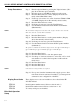
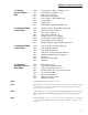
Step 1. For all RIO board options (except for the last device) make
sure the dip switches are set to the OFF position. (See Fig. 2-
1)
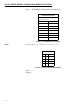
FIG. 2-1 REMOTE I/O S1 DIP SWITCH SETTINGS (DEFAULT)
NOTE: The factory default setting is for both switches to be turned OFF. Also note that the
dip switches in Figure 2-1 have been rotated for illustration purposes.
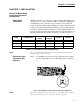
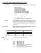
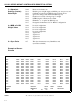
BAUD TERMINATION
MAX
NODES
MAX
LENGTH
SWITCH 1 SWITCH 2
57.6 K 150 Ohms 16 10,000 Feet ON OFF
115.2 K 150 Ohms 16 5,000 Feet ON OFF
230.4 K 82 Ohms 32 2,500 Feet OFF ON
TABLE 2-1: CABLE TERMINATION REQUIREMENTS
S1
ON OFF
12