
Instruction Manual


Chapter 4 - Discrete Transfers
4-3
1 = Remote
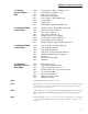
Function Status
Byte
bit 0 Force display to Rate-of-Change mode
bit 1 Add current net weight to total
bit 2 Hold value on display
bit 3 Hold option card updates
bit 4 Force display to Net Weight mode
bit 5 Toggle lbs/kg
bit 6 Acquire Tare
bit 7 Print Request (RS232 and BCD ports)
2 = Indicator Group
2 Status Byte
bit 0 Weight currently displayed in pounds units
bit 1 Zero Track feature enabled
bit 2 Reserved for future use
bit 3 Current Gross Weight = 0
bit 4 Weight in motion, i.e. changing
bit 5 Gross Weight currently displayed
bit 6 Net Weight currently displayed
bit 7 Weight currently displayed in kilogram units
3 = Indicator Group
1 Status Byte
bit 0 Rate-of-Change currently displayed
bit 1 Setpoint Relay #2 active
bit 2 Setpoint Relay #1 active
bit 3 Peak Force (weight) currently displayed
bit 4 Totalized weight currently displayed
bit 5 Reserved
bit 6 Excitation Monitor Error
bit 7 Reserved
4 = Dipswitch
Settings (exterior)
Status Byte
bit 0 RE-calibrate toggle
bit 1 Option menu keypad lockout
bit 2 Setpoint menu keypad lockout
bit 3 Lb/Kg, Net/Gr, Tare, Zero keypad lockout
bit 4 Zero tracking enable
bit 5 Reserved for future use
bit 6 RS232 command lockout
bit 7 Multi-Drop enable
NOTE: If Blind Mode dip switches status not visible.
NOTE: The PLC will receive both words with each discrete read, but it is not guaranteed that
both words will be transferred as a unit. Both words will get transferred, but there
may be some delay between the two.
NOTE: For the PLC-2
®
series, you must use a 1772-SD2 scanner and the PLC-2
®
system to
allow communication with the HI 2151WC via block transfer. Use block transfers
only.
NOTE: For the SLC 5/02
®
or above processors, you must use a 1747-SN to allow communi-
cation with the HI 2151WC via discrete transfer. The 1747-SN does not support block
transfer.