
Instruction Manual

Chapter 5 - Block Transfers
5-5
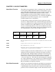
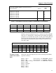
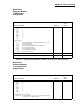
TABLE 5-3: BLOCK READ COMMAND NUMBER 2: SETPOINT RELAY PARAMETERS
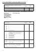
The three setpoint description bytes are constructed by first reading the
table above to determine the 1 and 0 pattern representing the weighing
parameter you would like the setpoint to monitor, then writing that pat-
tern below under the appropriate relay number. When patterns have
been written for all desired relays then read bytes A, B, and C across
from left to right.
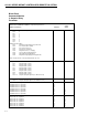
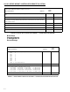
Example of Proper
Setpoint Description
Bytes
The proper setpoint description bytes for the following desired Relay
types are as follows:
Relay 1 = Gross Word 1, bits 8 - 15 = 0001 0000 = 10 (hex)
Relay 2 = Net Word 2, bits 0 - 7 = 1110 0101 = E5 (hex)
Relay 3 = Rate-of-Change Word 2, bits 8 - 15 = 0000 0110 = 06 (hex)
Relay 4 = Peak
Relay 5 = Totalizer
Relay 6 = Gross
Relay 7 = Gross
Relay 8 = Gross
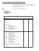
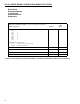
Setpoint value for setpoint #1
Setpoint value for setpoint #2
Setpoint value for setpoint #3
Setpoint value for setpoint #4
Setpoint value for setpoint #5
Setpoint value for setpoint #6
Setpoint value for setpoint #7
Setpoint value for setpoint #8
2
2
2
2
2
2
2
2
35
37
39
41
43
45
47
49
TOTAL NUMBER OF WORDS 51
BLOCK READ COMMAND NUMBER 2: Setpoint Relay Parameters
START
WORD DEFINITIONS: #WORDS WORD
Peak Force Net Weight Gross Weight Rate-of-Change Totalizer
Word 1, bits 8 - 1500001
Word 2, bits 0 - 700110
Word 2, bits 8 - 1501010
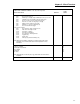
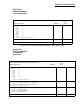
TABLE 5-4: SETPOINT DESCRIPTION BYTES
SETPOINT DESCRIPTION BYTES
Relay 8 Relay 7 Relay 6 Relay 5 Relay 4 Relay 3 Relay 2 Relay 1
Word 1, bits 8-15
Word 2, bits 0-7
Word 2, bits 8-15
TABLE 5-5: SETPOIINT DESCRIPTION BYTES