
Instruction Manual

HI 2151 SERIES WEIGHT CONTROLLERS REMOTE I/O OPTION
6-2
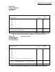
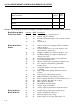
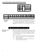
Block Write
Example
The following is an example using block write #51 to zero the scale.
Command #51 is made up of one word. Bits 0-7 represent the address
or the command number (00110011 = 51). To activate the scale func-
tion, toggle bit #13. This creates a word which has a decimal value of
8,243.
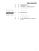
Math Conversion
Programs
Math conversion routines, written in ladder logic convert the twenty bit
integer data available from the HI 2151WC to a PLC floating point for-
mat. Conversely, routines can convert from Floating Point to integer.
To convert from integer to floating point, your ladder logic program
would follow these steps:
Step 1. Convert the lower sixteen bits into a floating point number.
Step 2. Test the seventeenth bit (bit 16) and if set, add 65,536 to the
floating point number.
Step 3. Test each subsequent bit and add the appropriate numeric
value to the floating point number.
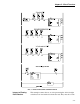
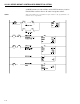
Bit 4 0 = Off
6
Relay #4 status (on/off)
Bit 5 1 = On Relay #3 status (on/off)
Bit 6 1 = On Relay #1 status (on/off)
Bit 7 0 = Off Relay #2 status (on/off)
Bit # Bit Status Hex Description
TABLE 6-2: RELAY STATUS
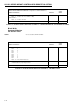
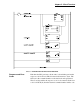
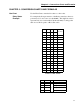
Bit # 15 14 131211109876543210
Decimal Value 32768 16384 8192 4096 2048 1024 512 256 128 64 32 16 8 4 2 1
ONE WORD
TABLE 6-3: BINARY TO DECIMAL CHART
Bit # 0010000000110011
TABLE 6-4: BLOCK WRITE EXAMPLE