
Owner's manual

HI 2151/30WC MANUAL
7-14
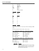
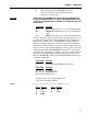
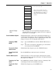
S Set point
DI Dipswitch
L LED Status
REL Relay
REM Remote
CROC
E Excitation Monitor
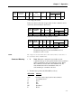
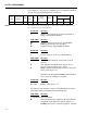
SUB-CMD Meaning
REL Relay
Bit RELAY
01 5
02 4
04 3
08 1
10 2
20 8
40 7
80 6
SUB-CMD Meaning
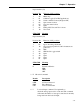
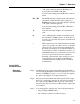
The L command returns a two-byte status, each bit describing the LED
status.
The values returned are the hex values of the two bytes.
Byte 1: LED STATUS, BYTE 1 Byte 2: LED STATUS, BYTE 2
Bit 0 - Pounds led Bit 0 - Rate of change led.
Bit 1 - Zero track led Bit 1 - Alarm #2 led.
Bit 2 - Not used Bit 2 - Alarm #1 led.
Bit 3 - Center zero led Bit 3 - Peak led.
Bit 4 - Motion led Bit 4 - Total led.
Byte 1: LED STATUS, BYTE 1 Byte 2: LED STATUS, BYTE 2
Bit 5 - Gross led Bit 5 - Not used
Bit 6 - Net led Bit 6 - Not used
Bit 7 - Kilograms led Bit 7 - Not used
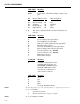
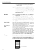
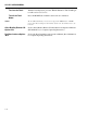
SUB-CMD
Meaning
DI The HI 2151/30WC will return two bytes for the dip
switches. Dip switch #1 is the one on the rear panel
and Dip Switch #2 is internal to the unit located on
the bottom power relay board.