
Owner's manual

Chapter 8 - Troubleshooting
8-29
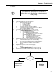
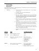
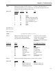
DIP 2 Indicates next display will be settings of If value is other than desired,
internal dipswitch S2 on power relay board. reset dipswitch segment and retest.
Settings represented by hexadecimal notation.
00 thru FF SWITCH VA L UE ON OFF
POSIT
801Spare
702Spare
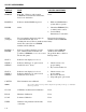
4 04 NBS Re-Call toggle switch
1 08 Ignore incoming checksums
2 10 On is averaged gross,
Off is instantaneous gross
320NBS
540Spare
680Spare
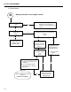
LC CNT = 0 - 8
SN1 xxxx-xxxx
“ “ “
SN8 xxxx-xxxx
NOTE: LC CNT SN1 through SN8 is for C2 only.
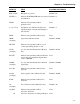
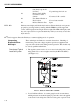
TAG 1 Indicates next display will be value of If options are not as desired,
software control options. Settings another memory key must be
represented by hexadecimal notation ordered. Contact Hardy
Instruments Customer Support
Department.
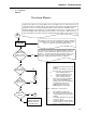
DISPLAY
TEST FAILURE SOLUTIONS
00 thru FF VALUE ON OFF
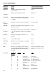
01 Bar-graph No bar-graph
02 Rate of change No ROC
04 Peak hold No peak hold
08 Hardy link No Hardy link
10 Optional relays No optional relays
20 Spare Spare
40 CAL SW override Normal CAL mode
80 Totalizer No totalizer
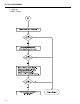
TAG 2 Indicates next display will be value of software control options.
00 thru FF VALUE
ON OFF
01 Spare Spare
02 Remote clear total No remote clear total
04 Remote clear peak No remote clear peak
08 Partial Setpoint Lock