
Owner's manual

Chapter 3 - Installation
3-3
Installing the HI 2151/
30WC in a Panel
Panel Cutout
Specifications
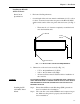
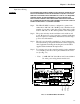
1. Enclosure Size Requirements.
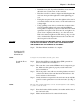
• Overall depth of the enclosure must be a minimum of 11.5" to allow
for the 2" clearance between the rear panel of the HI 2151/30WC
and the inside surface of the rear panel of the enclosure. (See Fig. 3-
1)
• There must be a 1" clearance completely around the bezel
and other installed units.
FIG. 3-1 2” REAR PANEL CLEARANCE REQUIREMENT
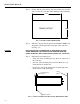
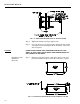
2. Dimensions of the enclosure cutout (See Fig. 3-2)
• 5.75" ± .06 (146.05mm ±1.52) Wide
• 3.09" ± .06 (78.49mm ±1.52) High
• All cutout surfaces must be deburred before installation of
the controller.
WARNING DO NOT MOUNT THE HI 2151/30WC CONTROLLER NEAR A HIGH MAG-
NETIC FIELD OR HIGH VAC POWER SOURCE. TO DO SO WILL EFFECT
THE PERFORMANCE OF THE CONTROLLER AND MAY RESULT IN
PROPERTY DAMAGE.
Installing the HI
2151/30WC Panel
Mount
Step 1. Ensure that all Electrostatic Discharge (ESD) precautions
have been taken before installation.
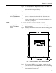
Step 2. The controller comes with a NEMA 4 rated compression gas-
ket. Make sure the gasket is properly seated in the bezel
before installation.
2.0"
Front Panel
Bezel
Rear
Panel