
Owner's manual

Chapter 3 - Installation
3-11
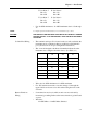
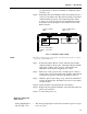
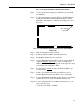
J5 Set Point 5 J6 Set Point 6
Pin 1 Lo Pin 1 Lo
Pin 2 Hi Pin 2 Hi
J7 Set Point 7 J8 Set Point 8
Pin 1 Lo Pin 1 Lo
Pin 2 Hi Pin 2 Hi
• Use 22 AWG minimum to 12 AWG maximum wire for J3 through
J8.
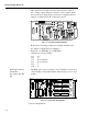
NOTE: See Output Option Board Installation for board installation procedures.
CAUTION
THE CONTACTS ON THE SOLID STATE RELAY WILL OPEN IF A POWER
FAILURE OCCURS. A LIT LED INDICATES THAT THE RELAY HAS BEEN
ACTIVATED.
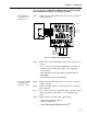
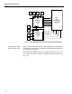
J3 Serial Port Wiring • The standard serial port J3 is located on the second board inside the
instrument and is configured either as an RS-232 or RS-422/485
port. (See Section 4.1 for port configuration instructions)
• The -A model designator in the model number indicates how the
instrument was configured from the factory. (See Table 3-1)
• Wire size: 22 AWG minimum to 12 AWG maximum
• For -WS wall mount models, route the wiring to J3 through the
upper left side enclosure access hole when facing the front of the
enclosure.
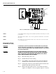
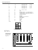
Remote Functions
Wiring
• Some functions are level conditions and some are activated by
momentary grounding. Both use the remote functions ground found
on pin 9.
•Wire Size:
22 AWG Min. to 12 AWG Max. Shielded
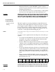
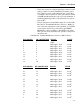
-A1 -A2 -A3
J3 RS-232 RS-422 RS-485
Pins Signal Signal Signal
1CtsTx+Tr+
2RtsTx-Tr-
3RxdRx+N/C
4TxdRx-N/C
5 Gnd Gnd Gnd
TABLE 3-1: FACTORY CONFIGURATION