
Owner's manual

HI 2151/30WC MANUAL
3-16
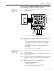
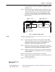
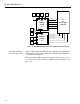
• This option has one output connector and uses pins 1 and 2 for +
and - voltage outputs and pins 5 and 6 for - and + current outputs.
• One current and voltage range is selected by configuring the two
jumpers on jumper block "W" of the analog board.
FIG. 3-12 ANALOG OUTPUT BOARD
• Both current and voltage outputs are available simultaneously.
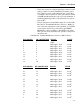
• For Jumper Configurations See Chapter 4.
• Wire Size: 22 AWG Min. To 12 AWG Max
• -B1 Option Connector Wiring:
J1-1 V+
J1-2 V-
J1-3 No Connection
J1-4 No Connection
J1-5 I-
J1-6 i+
BCD Option Board
Installation
Procedures -B2, -B5, -
B9
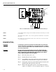
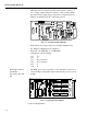
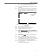
• The BCD option board. (See Fig. 3-13) is installed in option slot 2
only and will provide parallel output of the sensed gross, net, or tare
weight.
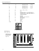
FIG. 3-13 PARALLEL BCD BOARD
Connector Requirements
0535-0406- REV- ANALOG OUT PWA
C1
U1
C4
RN 1
C3
C2
U2
U3
U4
C6
U6
S/N
U8
S
D
D
Q1
C5
U7
1
2
25
26
P1
U5
RN 2
C9
R1
R2
R3
C1 1
C8
CR1
C17
C18
C13 C16
C7
TP 1
C1 4C15
R4 R5
C19
R1 5
R1 4
R1 3
R1 2
R1 1
R1 0
R9
R8
R7
U9
R6
C20
OI
VR 2
-
+
+
+
VR 3
C21
C22
C24
C23
C25
U10
R1 6 R1 9
TP 2
ISO
GND
V
R4
CE
Q3
J1
1
6
D
Q
2
G
C
26
1
2
3
4
R1 7
R1 8
CR2
R
2
0
C
R
3
C
R
4
R
2
1
W
0535-0407- REV
C1
U1
1
2
P1
C3
U2
C2
U3
S
D
G
Q1
C5
TP 1
C4
++
+
ISO
GN D
RN 1
C6
C8
TP 2
+
I
O
G
C
7
ISO + 5V
C10
U6
VR 1
C9
U4
U5
C11
R1
U7
R2
R3
RN 2
W1
W2
C1 3C14
U11
C
1
2
C
1
6
C
1
5
U9
U
10
U
12
U8
U
13
U
14
U
15
C1 7C18C1 9C2 0
J1
39
40
BCD PWA S/N