
Owner's manual

Chapter 3 - Installation
3-17
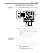
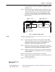
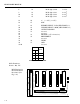
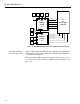
• The board connector is a 40 pin right angle connector termi-
nating to either a 37 pin D-subminiature assembly (option
B-2) a 40 pin connector with a 60-inch cable (option B-5),
or a 40 pin connector with a 24" cable (option B-9 used with
a Wall Mount Model) The B-5 option provides flexibility of
terminating BCD signal lines to the terminal board options
B-6 and B-7.
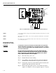
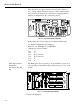
• The pin designations for the BCD output are noted in Cable
Pinouts List - Parallel BCD Board Connector to BCD Con-
nector. All data outputs have a drive capability of 15 LSTTL
loads (6 mA total) and use positive true logic. PRINT/
READY has a drive capability of 10 LSTTL loads (4mA).
This option board is electrically and optically isolated from
the main board.
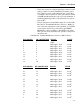
Cable Pinouts - Parallel BCD Board Connector to DB Connector
BCD BOARD DB CONNECTOR SIGNAL VA L UE
1 1 GND
3 2 BCD digit 1, bit 0 1 x 10°
5 3 BCD digit 1, bit 1 2 x 10°
7 4 BCD digit 1, bit 2 4 x 10°
9 5 BCD digit 1, bit 3 8 x 10°
11 6 BCD digit 2, bit 0 1 x 10
1
13 7 BCD digit 2, bit 1 2 x 10
1
15 8 BCD digit 2, bit 2 4 x 10
1
17 9 BCD digit 2, bit 3 8 x 10
1
19 10 BCD digit 3, bit 0 1 x 10
2
BCD BOARD DB CONNECTOR SIGNAL VA LU E
21 11 BCD digit 3, bit 1 2 x 10
2
23 12 BCD digit 3, bit 2 4 x 10
2
25 13 BCD digit 3, bit 3 8 x 10
2
27 14 BCD digit 4, bit 0 1 x 10
3
29 15 BCD digit 4, bit 1 2 x 10
3
31 16 BCD digit 4, bit 2 4 x 10
3
33 17 BCD digit 4, bit 3 8 x 10
3
35 18 BCD digit 5, bit 0 1 x 10
4
37 19 BCD digit 5, bit 1 2 x 10
4
2 20 BCD digit 5, bit 2 4 x 10
4
4 21 BCD digit 5, bit 3 8 x 10
4