
Owner's manual


HI 2151/30WC MANUAL
3-22
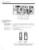
Dynamic Data
Exchange (DDE) I/O
Server -B14
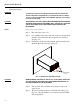
RS-232C- Requires an interface cable with a 9 pin or 25 pin serial port
female connector to connect to a computer. Wire the cable to the 5 pin
Phoenix connector J3 located on the rear panel of the weight controller.
Refer to Hardy Instruments optional DDE Installation and Operation
Manual, document number 0596-0221 for more details.
HI 215IT Series
Junction Boxes
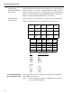
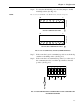
Refer to Fig. 3-11 Load Cell/Sensor Connections for specific details.
Wiring to Hardy Instruments Load Points and Load Sensors
TB9 J1 HI 2151/30WC
+EXC Red
+SEN Blue
-EXC Black
-SEN Brown
Shield
C2+ Grey
C2- Violet
+SIG Green
-SIG White
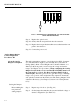
Set Point Relay Option
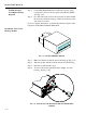
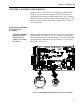
Board Installation -D2
The setpoint relay option board must be installed outside of the HI
2151/30WC. (See Fig. 3-18).
Step 1. Locate a clear, flat mounting area within five feet cable dis-
tance of the HI 2151/30WC.
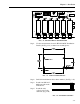
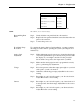
TB1, 3, 5,7
HI LPH
HI BB01
HI LPS
HI SB01
HI LPD
HI DSB01/2
HI LPT
HI SO1
+ EXC Green or
Green/Blue
Red Red Red
-EXC Black or
Black/Grey
Black Black Black
Shield Orange or
Yell ow
Orange or
Clear
Orange or
Clear
Orange or
Clear
TB2, 4, 6, 8
HI LPH
HI BB01
HI LPS
HI SB01
HI LPD
HI DSBO1/2
HI LPT
HI SO1
C2+ Grey Grey Grey Grey
C2 - Violet Violet Violet Violet
Sig + White Green Green Green
Sig - Red White White White