
Owner's manual


Chapter 3 - Installation
3-23
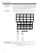
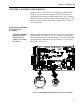
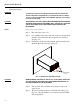
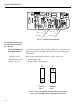
FIG. 3-18 SET POINT RELAY OPTION BOARD
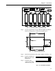
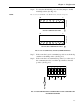
Step 1. Use the measurements shown in HI 2151/30WC Installation-
Details (See Fig. 3-19) to make four mounting holes.
FIG. 3-19 INSTALLATION DETAILS
Step 2. Drill 3/16-inch diameter holes where marked. (See Fig. 3-19)
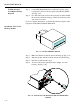
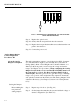
Step 3. Install four P/N 2815-
0063 standoffs in the
drilled holes.
Step 4. Install the relay
option board on the
standoffs. (Fig. 3-20)
FIG. 3-20 STANDOFF ASSEMBLY
U1
RN1
TP 1
+5V
1
N.O.
N.O.
O
N
S
P
3
S
P
4
S
P
5
S
P
6
S
P
7
S
P
8
12345678
12345678
U2
PWA-RELAY,
HI2151/30WC
S/N -
TP2 GND
J1
S1
RN2
1
DS3
DS4
DS5
DS6
DS7
DS8
K3 K4 K5 K6 K7 K8
F3 5 A F4 5 A F5 5A F6 5 A F7 5 A
F8 5 A
0
5
3
5
-
0
3
5
7
R
E
V
-
J3 J4 J5 J6
J7
J8
12