
Owner's manual


Chapter 4 - Configuration
4-3
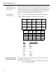
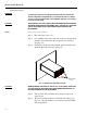
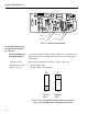
Step 6. To select the RS 422/485 ports, move the jumper to the RS
422/485 position. (See Fig. 4-3)
NOTE: The selection for the RS 422 or the RS 485 is done from the front panel.
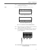
FIG. 4-3 RS-232 (DEFAULT), S422/485 JUMPER SETTINGS
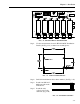
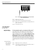
Step 7. If the controller is not in a termination position, set all the dip
switches to the OFF position. (See Fig. 4-4)
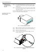
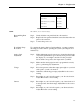
Step 8. If the controller is in a termination position (i.e. at the end of
the communication line) set all the dip switches to the ON
position. (See Fig. 4-5)
FIG. 4-4 NON TERMINATING CONTROLLER, ALL DIP SWITCHES SET
IN THE OFF POSITION
JP1
RS 232 JUMPER SETTING
JP1
RS 422/485 JUMPER SETTING
1
8
1
8
RS 422/485 RS 232 RS 422/485 RS 232
1
2
3
4
5
6
O
N