
Owner's manual


HI 2151/30WC MANUAL
4-6
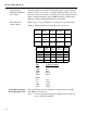
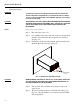
FIG. 4-6 ANALOG OUTPUT BOARD
Parallel BCD Board Print
Configuration Procedures -
B2, -B5, -B9
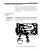
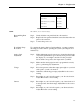
About the BCD Board
Print Output Signal
Some receivers require either a positive (high) pulse or a negative (low)
when printing. Select the jumper that meets the receiver input signal
requirements.
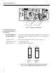
Jumper Location The switch is marked W1 W2 in the top center of the board.
Jumper Settings (See
Fig. 4-7 and 4-8)
• Positive Pulse = W1
• Negative Pulse = W2 (Default)
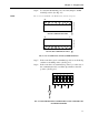
FIG. 4-7 BCD CARD JUMPER SETTING FOR POSITVE PULSE
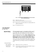
FIG. 4-8 BCD JUMPER SETTING FOR NEGATIVE PULSE
0535-0406- REV- ANALOG OUT PWA
C1
U1
C4
RN 1
C3
C2
U2
U3
U4
C6
U6
S/N
U8
S
D
D
Q1
C5
U7
1
2
25
26
P1
U5
RN 2
C9
R1
R2
R3
C1 1
C8
CR1
C1 7
C1 8
C13 C16
C7
TP 1
C1 4C1 5
R4 R5
C19
R1 5
R1 4
R1 3
R1 2
R1 1
R1 0
R9
R8
R7
U9
R6
C20
OI
VR 2
-
+
+
+
VR 3
C21
C22
C24
C23
C25
U10
R1 6 R1 9
TP 2
ISO
GND
V
R4
CE
Q3
J1
1
6
D
Q
2
G
C
26
1
2
3
4
R17
R18
CR2
R
2
0
C
R
3
C
R
4
R
2
1
W
Voltage Zero
Current Span
Voltage Span
Current Zero
W
1
W2
W1W2
Positive
Pulse
Negative
Pulse