
Owner's manual

HI 2151/30WC MANUAL
6-2
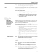
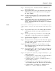
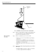
FIG. 6-1 PROPERLY INSTALLED LOAD CELL W/NO BINDING
Step 3. Check to see that nothing is coming in contact with the scale/
vessel other than service wires and piping that have been
properly mounted with flexible connectors.
Electrical Check
Procedures
Step 1. Check to see that there is power to the controller.
• If there is power to the controller The front panel display
should be lit.
• If an error message (ERREXC) appears in the display, it
means there is a problem in the system. See Troubleshoot-
ing Chapter 8 for corrective action.
• If the display appears with a value the unit is ready for cali-
bration.
Step 2. Typical Load Cell/Point Input/Output Measurements (EXC &
SIG Outputs)
• The HI 2151/30WC is designed to supply 5 vdc excitation
to as many as eight 350 ohm load cells/points.
Vessel
Direction of
the applied
load