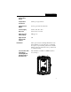
HI 2201LT Loop Powered Level Weight Transmitter For Hazardous Areas HI 2204LT Loop Powered Level Weight Transmitter OPERATION AND INSTALLATION MANUAL Corporate Headquarters 9440 Carroll Park Drive, Suite 150 San Diego, CA 92121 Phone: (858) 278-2900 FAX: (858) 278-6700 Web-Site: http://www.hardyinst.com Hardy Instruments Document Number: 0596-0138-01 Rev E Copyright November 1999 Hardy Instruments, Inc. All Rights Reserved. Printed in the U.S.A.
1-2
Table of Contents Table of Contents Overview - - - - - - - - - - - - - - - - - - Specifications - - - - - - - - - - - - - - - - Physical Dimensions - - - - - - - - - - - Power Requirement - - - - - - - - - - - Load Cell Excitation - - - - - - - - - - - Zero Offset Range - - - - - - - - - - - - Sensitivity - - - - - - - - - - - - - - - - Linearity - - - - - - - - - - - - - - - - - Operating Temperature Range - - - - - - Temperature Coefficient - - - - - - - - - Signal Current Ripple - - - - - - - - - - Power
HI 2201 LT ii
HI 2201LT/HI 2204LT Overview The model HI 2204LT Loop Powered Level Weight Transmitter and model HI 2201LT Loop Powered Level Weight Transmitter for Hazardous Areas furnish power to strain gage transducers, measure the return voltage, and adjust the 4-20 milli amp loop current to be proportional to the transducer signal. The HI 2201LT is Factory Mutual approved and safe to use in hazardous operating environments.
HI 2201LT/HI 2204LT HI 2204LT (14 VDC) to that of each receiving device (loop resistance x 20 ma). The Level Indicator applies power to each transducer in pulses a few milliseconds long at a rate of 90 pulses per second. The Level Indicator measures the voltage across the output terminals of the transducer with each power pulse, and it converts the average into a smooth current that varies with the transducer signal.
HI 2201LT/HI 2204LT Operating Temperature Range 0o C to +60o C (+32o F to +140o F) Temperature Coefficient 0.025% per degree Celsius Signal Current Ripple 20 mV p-p at 20 ma into 500 ohms Power Supply Rejection 0.015% (max) 20 to 30 V 0.
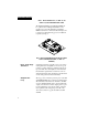
HI 2201LT/HI 2204LT FIG. 1 HI 2201LT/HI 2204 (-A3 OR -A5) IN NEMA 4 JUNCTION BOX/TOP VIEW The HI 2201/2204LT-A3 and HI 2201/2204LT-A5 Loop Powered Level Weight Transmitter comes mounted on a load cell summing board within a NEMA 4 junction box. The load cell summing board is designed to allow balancing pots to be installed if required. (See Fig. 2) FIG.
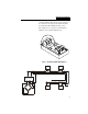
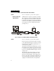
HI 2201LT/HI 2204LT The transmitter output loop can be wired with any two conductor shielded cable. The two inner conductors are connected to the output of the transmitter at the two terminals marked LOOP. (See Fig. 3 & 4) Note which wire is connected to each terminal to maintain correct polarity within the loop. FIG.
HI 2201LT/HI 2204LT FIG. 4 OUTPUT/POWER LOOP WIRING NOTE: Be sure to shield the tie point for CE compliance. Earth Ground and Signal Return “Earth Ground” is used here to indicate a point actually connected to a path into the Earth’s ground. The term “signal return” is used to indicate a return path for signals to the negative side of the power supply, or in the case of the output/loop, signal return means the more negative side of the voltage being measured. (See Figs.
HI 2201LT/HI 2204LT Precautions on Grounding 1. 2. NOTE: Only the one point where the loop is already grounded can accept a grounded lead. 3. 4. Isolation Do not connect the signal return to the earth ground at more than one point in the output/ power loop. Any receiver or electronic device inserted in the output/power loop must be designed so that the connections to the loop are isolated from ground. Do not connect the earth ground to the signal return in the transmitter input circuit.
HI 2201LT/HI 2204LT brations instructions before attempting to calibrate the instrument. Calibration Controls Coarse (Zero) The Coarse Control is used to remove large deadloads or offsets such as the weight of the scale’s platform, container or any other constant weight on the load cells which is part of the weighing equipment itself. This control can subtract as much as 65% of full scale from the transmitter’s output. Fine (Zero) This control is a fine offset adjustment.
HI 2201LT/HI 2204LT Step 2. Install a milli ammeter, in series, into the output/power loop of the transmitter. If a voltmeter is to be used for measurements, and a resistor for calibration is not already installed in the system, install a 100 ohm, +- 0.1%, 1/4 W resistor, in series, into the output/power loop of the transmitter. Voltmeter readings are show in parentheses. Step 3. If a voltmeter is used, attach the voltmeter across the 100 ohm resistor. Step 4.
HI 2201LT/HI 2204LT Trouble Shooting Procedures Malfunction: No Output Malfunction: No Change in Input Malfunction: Output Drifts 10 Step 7. Remove the calibration weight and recheck that the zero reading is still 4 ma (0.4 V). Adjust the FINE control if necessary. Step 8. Place the calibration weight back on the scale and recheck that the calibration reading is still correct. Adjust the SPAN control if necessary. Step 9.
HI 2201LT/HI 2204LT Factory Mutual (FM) Approval (HI 2201LT Only) The HI 2201LT is FM approved and instrinsically safe for Class I, II, III, Division I, Division II, Groups A,B,C,D,E,F and G hazardous locations in accordance with entity requirements and Hardy drawing No. 0582-0563. The HI 2201LT is approved with the MTL 705 Barrier (See Fig. 6) or with any other FM-approved barrier provided that the maximum entity parameters are met. (See Fig. 7) FIG. 6 MTL705 BARRIER FIG.
HI 2201LT/HI 2204LT 12