
Manual


HI 2201LT/HI 2204LT
10
Step 7. Remove the calibration weight and
recheck that the zero reading is still 4 ma
(0.4 V). Adjust the FINE control if neces-
sary.
Step 8. Place the calibration weight back on the
scale and recheck that the calibration read-
ing is still correct. Adjust the SPAN con-
trol if necessary.
Step 9. Repeat steps 7 & 8 until no further adjust-
ment is necessary to keep both measure-
ments within the system tolerances.
Step 10. Calibration is complete.
Trouble Shooting
Procedures
This section is intended to provide assistance in solv-
ing minor system problems.
Malfunction: No
Output
Checks to be made:
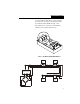
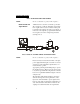
1. Check voltage at + & - loop connections. You
should get a reading of 15 VDC to 50 VDC.
2. Verify load cell connections.
3. Using an Oscilloscope, verify that you have a
pulsed 5 VDC between terminals labeled - & +
excitation.
Malfunction: No
Change in Input
Checks to be made:
1. Load Cell signal output below original setting. If
the signal level returned by the Load Cells is
below the previous deadload setting, measure
approximately 2.3 ma between the loop + & - ter-
minals.
2. Load Cell signal output above original setting. If
the signal level returned by the load cell is above
the previous Span setting, measure approxi-
mately 23 ma between the loop + & - terminals.
Malfunction:
Output Drifts
Checks to be made:
1. Verify load cell connections.
2. Verify Power Supply output and confirm that it is
outputting a constant voltage.