
Manual

QUICK INSTALLATION GUIDE
Mechanical Installation
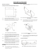
Installing the HI 3010 Filler/Dispenser/IBC in a Panel
FIG. 1 PANEL CUTOUT DIMENSIONS
Step 1. Make sure that all Electrostatic Discharge (ESD) precautions
are taken before and during installation.
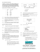
Step 2. Slide the gasket over the rear of the instrument until the gasket
is flush with the back side of the front panel. (See Fig.2)
FIG. 2 PANEL MOUNT INSTALLATION
Step 3. Gently slide the Filler/Dispenser with the gasket into the cut-
out in the enclosure front panel or door until the gasket is flush
with the enclosure front panel. (See Fig. 3-4) Be sure to secure
the instrument with both hands when installing.
Step 4. Gently slide the Panel Mount Collar over the rear of the instru-
ment. (See Fig. 2)
Step 5. Push the captive screws through the holes in the Enclosure
Front Panel and install the screws into the tapped holes on the
instrument until the screws are finger tight.
Step 6. Use a slotted head screwdriver and tighten each screw until the
instrument is snug and the compression gasket is tight against
the panel. Use a torque screw driver and torque each screw to
10 inch/pounds. DO NOT OVERTIGHTEN!
Installing the HI 3010 Filler/Dispenser/IBC in a Swivel/
Wall Mount
NOTE: When wall mounted, the unit should support a 14
pound weight for one minute without coming loose or
damaging the equipment.
Step 1. Use four (4) 1/4 x 20 fasteners to fasten the swivel mount to a
horizontal surface. (See Fig. 3)
FIG. 3 INSTALLING THE SWIVEL MOUNT TO A HORIZON-
TAL SURFACE
Step 2. Place the Filler/Dispenser between the Swivel Mount brackets
so that the threaded holes in the instrument are aligned with
the slots in the Swivel bracket. (See Fig.4)
FIG. 4 FILLER/DISPENSER INSTALLING IN A SWIVEL
MOUNT
Step 3. Screw the two fastener knobs into the threaded holes on each
side of the Filler/Dispenser until the brackets are snug against
the instrument. (See Fig. 5)
Load Point Installation
FIG. 5 REAR PANEL/LOAD POINT CONNECTIONS