
Owner manual


Table Of Contents
- HI 3000 Series
- Operation and Installation Manual
- Table of Contents
- Table of Contents
- Table of Illustrations
- Communications
- Cabling
- Network
- Security
- HI 3001
- Glossary of terms
- Index
- Table of Illustrations
- Communications
- Cabling
- Network
- Security
- HI 3001
- communications: installation & Operation
- Overview
- Communication Option Cards
- Remote I/O
- ControlNet
- Profibus
- MOD-Bus/TPC/IP
- OPC
- EtherNet/IP™
- Allen-Bradley Remote I/O
- Allen-Bradley License
- Common Applications
- Monitoring Weighing Parameters
- Short Glossary of Terms
- Tare Value
- Remote I/O Board Cable Termination Dip Switch Configuration
- About Cable Termination
- Dip Switch Settings
- Installing the RIO Option Board
- Connector Pin Out
- LED Indicators
- Removing the Remote I/O Option Card
- Remote I/O Configuration Procedures from the Front Panel
- Remote I/O Configuration Procedures from the Web Page
- FIG. 13: instrument home page/selecting configuration
- FIG. 14: configuration - options page/ selecting view remote i/o configuration
- FIG. 15: remote i/o configuration page
- FIG. 16: remote i/o configuration/ selecting baud rate
- FIG. 17: remote i/o configuration/ selecting rack size
- FIG. 18: remote i/0 configuration/ selecting quarter
- FIG. 19: Remote i/o configuration/ selecting last quarter
- Discrete Remote I/O Mapping
- About Discrete Remote I/O Mapping
- General Information
- For Reads:
- Mapping
- cabling: installation
- General Introduction to Cabling
- Unpacking
- Input Power Wiring
- Digital Input Wiring
- Output Relay Wiring
- Load Point Connections
- -JB Option Wiring
- Ethernet Cable Connection and Setup
- FIG. 26: rear panel/ethernet RJ 45 connection
- FIG. 27: configuration menu/selection setup
- FIG. 28: setup menu
- FIG. 29: setup menu/ethernet sub-menu
- FIG. 30: ethernet menu/default ip address
- FIG. 31: enter IP address in browser address field
- FIG. 32: web page
- Setting the IP Address for the Blind Remote
- Setting or Changing the IP Address using the Ethernet
- DeviceNet Connection and Setup From the Front Panel
- ControlNet Option Card Installation
- Removing the ControlNet Option Card
- ControlNet Connection and Setup
- Hardware Requirements:
- Software Requirements:
- Setting the ControlNet Node Address from the Front Panel
- Activating ControlNet and Setting the ControlNet Node Address from the Web Page
- FIG. 57: home page/selecting configuration
- FIG. 58: configuration page/selecting options
- FIG. 59: options page/selecting view controlnet configuration
- FIG. 60: controlnet page/activaTING CONTROLNET
- FIG. 61: controlnet configuration page/ entering node address
- FIG. 62: ControlNet configuration/entering node address
- LED Status Indicators
- EtherNet/IP™ Option Card Installation
- Removing the EtherNet/IP Option Card
- Profibus Option Card Installation
- Profibus Connection and Setup
- Removing the Profibus Option Card
- Analog Output Option Card Installation
- Removing the Analog Option Card
- Rear Cover Installation (HI 3000-RC)
- Installing the HI 3000-RC Rear Cover
- Network: Installation
- About Networks
- Simple Ethernet Network (See Fig. 90)
- Hardy Control-Link Ethernet Network
- FIG. 97: Hardy control-link Ethernet Network
- Materials Required
- Setting Node Addresses for HI 3000 Series Instruments from the Browser
- FIG. 98: filler/dispenser home page/ selecting configuration
- FIG. 99: configuration page/selecting hardy control-link
- FIG. 100: configuration - hardy control- link page
- FIG. 101: configuration - hardy control- link/instrument selection pull down list
- FIG. 102: Configuration page with instruments not assigned a node address
- FIG. 103: selected instrument with IP address in ip address field
- FIG. 104: hi-3010 (IP Address 192.168.110.68) assigned to node 0
- FIG. 105: selected instrument with IP address in ip address field
- FIG. 106: hi-3010 (IP Address 192.168.110.24) assigned to node 1
- FIG. 107: instruments assigned to node 0 through node 7
- FIG. 108: saving the configuration
- FIG. 109: transferring the node configuration from node 0 to node 1
- Using the Ping Tool
- Devicenet Network Setup
- RSNetWorx Setup for HI 3000 Series Instruments
- FIG. 110: selecting EDS wizard
- FIG. 111: eds wizard dialog box
- FIG. 112: selecting “register an eds file”
- FIG. 113: selecting the hardy eds file
- FIG. 114: selecting the hardy eds file
- FIG. 115: eds file installation test results dialog box
- FIG. 116: change graphic image dialog box
- FIG. 117: Final Task summary dialog box
- FIG. 118: Hardware/vendor/hardy instruments inc. installed
- FIG. 119: graph/hardy filler icon
- RSNetWorx Setup for HI 3000 Series Instruments
- Slave Mode Setup
- Building a Scanlist in RSNetWorx
- ControlNet Network Setup
- RSNetWorx Setup for HI 3000 Series Instruments with ControlNet Option Card
- Schedule the Network Using RSNetWorx for ControlNet
- Verify the Network Properties
- Survey the Network for Connected Devices
- Schedule the Network and Save the Configuration
- Selecting the ControlNet Node Address from the Front Panel
- Selecting the ControlNet Node Address from the Web Page
- PROFIBUS-DP Network Setup
- Initialization Process
- Profibus-DP .GSD File
- Pre-Initialization Procedures
- Initialization Procedures
- FIG. 141: hardware catalog/selecting anybus-s pdp folder
- FIG. 142: anybus-s pdp parameters dialog box
- FIG. 143: selecting the Input and output size
- FIG. 144: anybus-s pdp appears in the network
- FIG. 145: downloading hi 3000 series configuration
- FIG. 146: select destination module dialog box
- FIG. 147: select station address dialog box
- FIG. 148: downloading configuration prompt
- FIG. 149: initialization complete
- Selecting the Profibus Node Address from the Front Panel
- Selecting the Profibus Node Address from the Web Page
- MODBUS - TCP/IP Over Ethernet
- About MODBUS/TCP/IP Over Ethernet
- Installing MODBUS
- Enabling MODBUS in the HI 3000 Module
- Installing Hardy Modbus-Link
- FIG. 164: hardy modbus-link display
- FIG. 165: hardy modbus-link/selecting connect
- FIG. 166: tcp/ip connection display
- FIG. 167: tcp/ip connection display/ selecting tcp/ip
- FIG. 168: tcp/ip connection display/ entering the ip address
- FIG. 169: mapping display/clicking on destination - scratchpad: HFO4 (Hardy Float Out - word 4)
- FIG. 170: mapping display/selecting destination - scratchpad: HFO4
- FIG. 171: mapping display/selecting source - MFI0 (Modbus float IN - word 0)
- FIG. 172: mapping display/mapping the source to the destination
- FIG. 173: mapping display/HFO - float variables/entering a value for word 0
- FIG. 174: hardy modbus-link display/ selecting display/float inverse
- HI3000bk-P2.pdf
- FIG. 175: hardy modbus-link display/555.0000 appears
- FIG. 176: hardy modbus-link display/ selecting button 23 - read/write multiple registers
- FIG. 177: hardy modbus-link display/ writer multiple registers display
- FIG. 178: hardy modbus-link/enter value display
- FIG. 179: hardy modbus-link/enter value display/entering 999
- FIG. 180: hardy modbus-link/write multiple registers/sending new value
- FIG. 181: Response OK pop up
- FIG. 182: mapping display with value “999.0000” received from the Hardy Modbus-link client
- Using MODBUS with Excel®
- OPC Network Setup
- FIG. 183: OPC heterogeneous computing environment
- OPC SERVER
- Configuring Omniserver to Communicate with an HI 3000 Module
- FIG. 185: omniserver configuration dialog box
- FIG. 186: Omniserver configuration dialog box
- FIG. 187: Winsock device configuration/ default parameters
- FIG. 188: winsock configuration/entering hi 3000 setup parameters
- FIG. 189: pinging hi 3000 module/connection indicated
- FIG. 190: HI 3000 device icon with ip address
- FIG. 191: protocols dialog box
- FIG. 192: protocol definition/double or right click on protocol settings
- FIG. 193: protocols definition dialog box/ creating protocol name and description
- FIG. 194: protocol definition/binary formats page
- FIG. 195: protocols definition
- FIG. 196: protocol settings with new protocol definitions
- FIG. 197: selecting topics icon
- FIG. 198: topics page/selecting a new topic
- FIG. 199: topic definition dialog box/ creating topic definition
- FIG. 200: topic definition/variables page
- FIG. 201: topic definition/hardyfloat icon
- FIG. 202: protocol page/highlighting hardyopc_float
- FIG. 203: protocol page/selecting new item
- FIG. 204: item definition dialog box
- FIG. 205: item definition
- FIG. 206: item definition/entering fO00
- FIG. 207: item definition
- FIG. 208: protocol page/item list entered
- FIG. 209: item definition/Send data trigger
- FIG. 210: item definition/sequence number in
- FIG. 211: item definition/sequence number out
- FIG. 212: protocol page/selecting host message
- FIG. 213: host message definition
- FIG. 214: request page with no request message
- FIG. 215: selecting www link
- FIG. 216: hi 3000 support site
- FIG. 217: Eps files/selecting opc float dpd file
- FIG. 218: file download dialog box
- FIG. 219: save as dialog box/selecting program files
- FIG. 220: program files/selecting descartes omniserver
- FIG. 221: omniserver folder saving dpd file
- FIG. 222: host message
- FIG. 223: chains and triggers page
- FIG. 224: protocol definition/selecting unsolicited messages
- FIG. 225: unsolicited message definition page
- FIG. 226: unsolicited message definition/ name and description entered
- FIG. 227: unsolicited message definition/ received page
- FIG. 228: unsolicited message definition/ received message
- Setting Up OPC Communication with a Client
- About OPC Clients
- FIG. 229: wonderware/selecting wwclient
- FIG. 230: wonderware/close the log viewer
- FIG. 231: wwclient/selecting create connection
- FIG. 232: create connection dialog box
- FIG. 233: create connection dialog box
- FIG. 234: iot connection
- FIG. 235: item dialog box
- FIG. 236: wwclient/list of iot connections
- FIG. 237: WWClient/list of items (FI00)
- FIG. 238: wonderware/opening windowmaker
- FIG. 239: windowmaker dialog box
- FIG. 240: windowmaker/opening a new window
- FIG. 241: window maker/creating a new window
- FIG. 242: Machine Monitor window entering ###.####
- FIG. 243: windowmaker/selecting animation links
- FIG. 244: windowmaker/object type dialog box
- FIG. 245: Windowmaker/access name dialog box
- FIG. 246: windowmaker/add access name dialog box
- FIG. 247: windowmaker/selecting tagname dictionary
- FIG. 248: windowmaker/creating a tag name
- FIG. 249: windowmaker/select tag dialog box/selecting ips
- FIG. 250: newly created window
- FIG. 251: windowmaker/selecting runtime
- FIG. 252: windowmaker/runtime value
- Setting up the Output to the OPC Server and the Client from the HI 3000 Module
- Adding the HI 3000 Module to the Hardy Control- Link (TCP/IP) Network
- FIG. 253: HI 3030 Main web page/selecting configuration
- FIG. 254: Configuration page/selecting hardy control link
- FIG. 255: hardy control-link page/ selecting listed hi 3000 module ip address
- FIG. 256: hardy control-link page selecting node 5
- FIG. 257: selected instrument’s ip address appears in the node 5 text field
- FIG. 258: saving the node address assignment
- FIG. 259: ok message box
- FIG. 260: Node IP Address configured
- Mapping Parameters to the HardyFloat Output Table
- FIG. 261: configuration page/selecting mapping setup
- FIG. 262: mapping setup page 1
- FIG. 263: mapping setup page 1/selecting hardy control-link float out
- FIG. 264: hardy control-link float out selected/word 0
- FIG. 265: hardy control-link float out/ word 0 (EFO0) set as mapping destination
- FIG. 266: mapping setup 2/source selection page
- FIG. 267: mapping setup 2/selecting process data/gross weight
- FIG. 268: process data/gross weight channel 1 (HF14)
- FIG. 269: Gross Weight-channel 1 assigned to hardy control-link float out
- FIG. 270: gross weight assigned to hardy control-link float out
- FIG. 271: hardy control-link float out/ word 2
- FIG. 272: hardy control-link float out/ word 2 selected as destination
- FIG. 273: mapping page 2 selecting net weight
- FIG. 274: process data/selecting net weight/channel 1
- FIG. 275: current mappings/net weight/ channel 1 (HFI8) assigned to hardy Control-link float out (EFO2)
- FIG. 276: Net weight assigned to hardy control-link float out
- FIG. 277: hardy control-link float out/ word 4
- FIG. 278: hardy control-link float out/ word 4 selected as destination
- FIG. 279: mapping page 2 selecting gross weight
- FIG. 280: process data/selecting Gross weight/channel 2
- FIG. 281: current mappings/gross weight/ channel 2 (HFI8) assigned to hardy Control-link float out/word 4 (EFO4)
- FIG. 282: gross weight assigned to hardy control-link float out
- FIG. 283: hardy control-link float out/ word 6
- FIG. 284: hardy control-link float out/ word 4 selected as destination
- FIG. 285: mapping page 2 selecting net weight
- FIG. 286: process data/selecting Net weight/channel 2
- FIG. 287: current mappings/gross weight/ channel 2 (HFI9) assigned to hardy Control-link float out/word 4 (EFO4)
- FIG. 288: gross weight assigned to hardy control-link float out
- FIG. 289: selecting an expanded map
- FIG. 290: expanded map dialog box
- Configuring EtherNet/IP Using RSLogix5000®
- Mapping
- E-Mail: Configuration and Operation
- Overview
- Understanding IP Addresses
- Glossary of E-Mail Terms
- Configuring the E-Mail Server
- FIG. 296: instrument home page/selecting configuration
- FIG. 297: configuration web page/selecting E-mail
- FIG. 298: e-mail configuration web page
- Entering the Mail Server Name from the Front Panel
- Continuing E-Mail Configuration from the Web Page
- Configuring Standard E-Mail
- Configuring Custom E-Mail
- About Custom E-Mail
- About Tokens
- FIG. 309: list of parameter descriptions and hexadecimal numbers
- FIG. 310: Map dictionary
- FIG. 311: expanded view of entered tokens
- FIG. 312: configuration web page/ selecting mapping setup
- FIG. 313: mapping setup1/sending custom e- mail
- FIG. 314: mapping Setup 1/selecting send email
- FIG. 315: entering email number
- FIG. 316: send email #0 entered in the equation
- FIG. 317: mapping setup 2 page
- FIG. 318: selecting local inputs
- FIG. 319: selecting local input #1
- FIG. 320: equation entered (HO3.0=HI0.0)
- FIG. 321: e-mail mapping complete
- Testing E-Mail
- Setting up Filters in E-mail Applications
- security: setup
- Overview
- Security Levels
- Setting up Passwords from the Front Panel
- Setting up Passwords from the Browser
- FIG. 327: home page/selecting configuration
- FIG. 328: configuration page/selecting security
- FIG. 329: enter network password dialog box
- FIG. 330: password authentication failed
- FIG. 331: configuration/security page
- FIG. 332: configuration - security page typing passwords
- FIG. 333: configuration - security/ selecting security level for a menu
- FIG. 334: configuration - security/ parameters set for security levels
- Log On Procedures
- HI 3001: Master Display
- Glossary of terms
- Accuracy
- alarm
- appurtenance
- Baud rate
- bi-directional
- capacity
- Check weighing
- clear key
- dead band
- dead load
- decimal point position
- dispenser
- display
- engineering units
- electrostatic discharge
- enter key
- eprom
- error
- even
- excitation
- filler
- full-scale
- graduation size
- gross weight
- IBC
- Internet
- Intranet
- Kilograms
- Levelling
- led
- load cell
- menu
- menu driven
- microprocessor
- midpoint linearity correction
- motion
- nema 4
- nema 4x
- Node
- net weight
- non-linearity
- number of readings per average
- odd
- option
- option slot
- parity
- pounds
- POP
- preact
- previous key
- prompts
- Protocol
- ram
- rate of change (ROC)
- repeatability
- resolution
- rom
- rts
- rxd
- scale capacity
- secure memory module (SMM)
- set point
- span
- tag
- tare
- temperature coefficient
- time base
- Token
- transmitter span
- transmitter zero
- ttl
- txd
- update rate
- zero
- zero calibration
- zero tolerance
- Index
HI-3000 Series 2
Operation and Installation
dard on many Allen-Bradley programmable controllers.
Setting each address and baud rate in the instrument, con-
necting three wires, and writing some ladder logic is all that
is needed to begin communicating weighing parameters to
and from an HI 3000 Series controller.
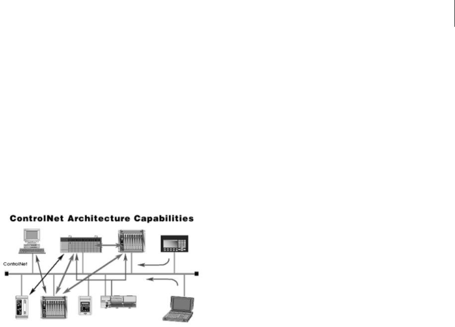
ControlNet
ControlNet enables multiple controllers to control I/O on the
same wire and permits multicast of both inputs and peer-to-
peer data, reducing traffic on the wire and increasing system
performance. (See Fig. 1)
FIG. 1: CONTROLNET ARCHITECTURE
ControlNet is highly deterministic and repeatable. These are
important requirements to ensure dependable, synchronized
and coordinated real-time performance. Determinism is the
ability to reliably predict when data will be delivered, and
repeatability ensures that transmit times are constant and
unaffected by devices connecting to, or leaving, the network.
These capabilities are further enhanced with user selectable
I/O and controller interlocking update times to match appli-
cation requirements.
ControlNet meets the requirements of real-time, high speed
applications at the Automation and Control Layer and inte-
grates complex control systems such as batch control sys-
tems, weigh process control systems and systems with
multiple controllers and human-machine interfaces.
Profibus
The Profibus-DP Communication Profile is designed for
efficient data exchange at the field level. The central automa-
tion devices, such as PLC/PC or process control systems,
communicate through a fast serial connection with distrib-
uted field devices such as I/O, drives and valves, as well as
measuring transducers. Data exchange with the distributed
devices is mainly cyclic. The communication functions
required for this are defined by the basic DP functions in
accordance with the EN 50 170 standard. In addition to these
basic functions, DP also offers extended acyclic communica-
tion services for the parameterization, operation, monitoring
and alarm handling of intelligent field devices. Loading the
*.GSD file and setting the Node Address and Input and Out-
put Sizes is all you need to begin communicating weighing
parameters to and from an HI 3000 Series controller to a
PLC, PC or DCS system controller.
MOD-Bus/TPC/IP
TCP/IP is the common transport protocol of the Internet and
is actually a set of layered protocols, providing a reliable
data transport mechanism between machines. Ethernet has
become the de facto standard of corporate enterprise systems
and it has also become the de facto standard for factory net-
working. Ethernet has matured to the point that the cost of
implementing this network solution has been dropping to
where its cost is commensurate with those of today's field-
buses. Using Ethernet TCP/IP in the factory allows true inte-
gration with the corporate Intranet and MES systems that
support your factory.
Combining a versatile, scaleable, and ubiquitous physical
network (Ethernet) with a universal networking standard
(TCP/IP) and a vendor-neutral data representation (MOD-
BUS
®
) gives a truly open, accessible network for exchange
of process data. It is also extremely simple to implement for
any device that supports TCP/IP sockets.
Simplicity: MODBUS
®
TCP/IP simply takes the MOD-
BUS
®
instruction set and wraps TCP/IP around it. If you
already have a MODBUS
®
driver and if you understand
Ethernet and TCP/IP sockets, you can in short period of
time, have a driver up and running and talking to a PC.
There are no exotic chipsets required to be purchased from
vendors, and you can use standard PC Ethernet cards to talk
to your implemented device. As the cost of Ethernet falls,
you benefit from the price reduction of the hardware, and as
the performance improves from 10 to 100 Mbit and soon to 1
Gbit, your technology moves with it protecting your invest-
ment.
NOTE: Mod-BUS
®
is a registered trademark of Sch-
neider Automated Inc.
OPC
OLE for Process Control (OPC) enables an HI 3000 module
to communicate with any device that supports OLE/COM.
The architecture is designed to utilize the Microsoft distrib-
uted OLE technology (DCOM) to facilitate clients interfac-
ing to remote servers.