
Owner manual


Table Of Contents
- HI 3000 Series
- Operation and Installation Manual
- Table of Contents
- Table of Contents
- Table of Illustrations
- Communications
- Cabling
- Network
- Security
- HI 3001
- Glossary of terms
- Index
- Table of Illustrations
- Communications
- Cabling
- Network
- Security
- HI 3001
- communications: installation & Operation
- Overview
- Communication Option Cards
- Remote I/O
- ControlNet
- Profibus
- MOD-Bus/TPC/IP
- OPC
- EtherNet/IP™
- Allen-Bradley Remote I/O
- Allen-Bradley License
- Common Applications
- Monitoring Weighing Parameters
- Short Glossary of Terms
- Tare Value
- Remote I/O Board Cable Termination Dip Switch Configuration
- About Cable Termination
- Dip Switch Settings
- Installing the RIO Option Board
- Connector Pin Out
- LED Indicators
- Removing the Remote I/O Option Card
- Remote I/O Configuration Procedures from the Front Panel
- Remote I/O Configuration Procedures from the Web Page
- FIG. 13: instrument home page/selecting configuration
- FIG. 14: configuration - options page/ selecting view remote i/o configuration
- FIG. 15: remote i/o configuration page
- FIG. 16: remote i/o configuration/ selecting baud rate
- FIG. 17: remote i/o configuration/ selecting rack size
- FIG. 18: remote i/0 configuration/ selecting quarter
- FIG. 19: Remote i/o configuration/ selecting last quarter
- Discrete Remote I/O Mapping
- About Discrete Remote I/O Mapping
- General Information
- For Reads:
- Mapping
- cabling: installation
- General Introduction to Cabling
- Unpacking
- Input Power Wiring
- Digital Input Wiring
- Output Relay Wiring
- Load Point Connections
- -JB Option Wiring
- Ethernet Cable Connection and Setup
- FIG. 26: rear panel/ethernet RJ 45 connection
- FIG. 27: configuration menu/selection setup
- FIG. 28: setup menu
- FIG. 29: setup menu/ethernet sub-menu
- FIG. 30: ethernet menu/default ip address
- FIG. 31: enter IP address in browser address field
- FIG. 32: web page
- Setting the IP Address for the Blind Remote
- Setting or Changing the IP Address using the Ethernet
- DeviceNet Connection and Setup From the Front Panel
- ControlNet Option Card Installation
- Removing the ControlNet Option Card
- ControlNet Connection and Setup
- Hardware Requirements:
- Software Requirements:
- Setting the ControlNet Node Address from the Front Panel
- Activating ControlNet and Setting the ControlNet Node Address from the Web Page
- FIG. 57: home page/selecting configuration
- FIG. 58: configuration page/selecting options
- FIG. 59: options page/selecting view controlnet configuration
- FIG. 60: controlnet page/activaTING CONTROLNET
- FIG. 61: controlnet configuration page/ entering node address
- FIG. 62: ControlNet configuration/entering node address
- LED Status Indicators
- EtherNet/IP™ Option Card Installation
- Removing the EtherNet/IP Option Card
- Profibus Option Card Installation
- Profibus Connection and Setup
- Removing the Profibus Option Card
- Analog Output Option Card Installation
- Removing the Analog Option Card
- Rear Cover Installation (HI 3000-RC)
- Installing the HI 3000-RC Rear Cover
- Network: Installation
- About Networks
- Simple Ethernet Network (See Fig. 90)
- Hardy Control-Link Ethernet Network
- FIG. 97: Hardy control-link Ethernet Network
- Materials Required
- Setting Node Addresses for HI 3000 Series Instruments from the Browser
- FIG. 98: filler/dispenser home page/ selecting configuration
- FIG. 99: configuration page/selecting hardy control-link
- FIG. 100: configuration - hardy control- link page
- FIG. 101: configuration - hardy control- link/instrument selection pull down list
- FIG. 102: Configuration page with instruments not assigned a node address
- FIG. 103: selected instrument with IP address in ip address field
- FIG. 104: hi-3010 (IP Address 192.168.110.68) assigned to node 0
- FIG. 105: selected instrument with IP address in ip address field
- FIG. 106: hi-3010 (IP Address 192.168.110.24) assigned to node 1
- FIG. 107: instruments assigned to node 0 through node 7
- FIG. 108: saving the configuration
- FIG. 109: transferring the node configuration from node 0 to node 1
- Using the Ping Tool
- Devicenet Network Setup
- RSNetWorx Setup for HI 3000 Series Instruments
- FIG. 110: selecting EDS wizard
- FIG. 111: eds wizard dialog box
- FIG. 112: selecting “register an eds file”
- FIG. 113: selecting the hardy eds file
- FIG. 114: selecting the hardy eds file
- FIG. 115: eds file installation test results dialog box
- FIG. 116: change graphic image dialog box
- FIG. 117: Final Task summary dialog box
- FIG. 118: Hardware/vendor/hardy instruments inc. installed
- FIG. 119: graph/hardy filler icon
- RSNetWorx Setup for HI 3000 Series Instruments
- Slave Mode Setup
- Building a Scanlist in RSNetWorx
- ControlNet Network Setup
- RSNetWorx Setup for HI 3000 Series Instruments with ControlNet Option Card
- Schedule the Network Using RSNetWorx for ControlNet
- Verify the Network Properties
- Survey the Network for Connected Devices
- Schedule the Network and Save the Configuration
- Selecting the ControlNet Node Address from the Front Panel
- Selecting the ControlNet Node Address from the Web Page
- PROFIBUS-DP Network Setup
- Initialization Process
- Profibus-DP .GSD File
- Pre-Initialization Procedures
- Initialization Procedures
- FIG. 141: hardware catalog/selecting anybus-s pdp folder
- FIG. 142: anybus-s pdp parameters dialog box
- FIG. 143: selecting the Input and output size
- FIG. 144: anybus-s pdp appears in the network
- FIG. 145: downloading hi 3000 series configuration
- FIG. 146: select destination module dialog box
- FIG. 147: select station address dialog box
- FIG. 148: downloading configuration prompt
- FIG. 149: initialization complete
- Selecting the Profibus Node Address from the Front Panel
- Selecting the Profibus Node Address from the Web Page
- MODBUS - TCP/IP Over Ethernet
- About MODBUS/TCP/IP Over Ethernet
- Installing MODBUS
- Enabling MODBUS in the HI 3000 Module
- Installing Hardy Modbus-Link
- FIG. 164: hardy modbus-link display
- FIG. 165: hardy modbus-link/selecting connect
- FIG. 166: tcp/ip connection display
- FIG. 167: tcp/ip connection display/ selecting tcp/ip
- FIG. 168: tcp/ip connection display/ entering the ip address
- FIG. 169: mapping display/clicking on destination - scratchpad: HFO4 (Hardy Float Out - word 4)
- FIG. 170: mapping display/selecting destination - scratchpad: HFO4
- FIG. 171: mapping display/selecting source - MFI0 (Modbus float IN - word 0)
- FIG. 172: mapping display/mapping the source to the destination
- FIG. 173: mapping display/HFO - float variables/entering a value for word 0
- FIG. 174: hardy modbus-link display/ selecting display/float inverse
- HI3000bk-P2.pdf
- FIG. 175: hardy modbus-link display/555.0000 appears
- FIG. 176: hardy modbus-link display/ selecting button 23 - read/write multiple registers
- FIG. 177: hardy modbus-link display/ writer multiple registers display
- FIG. 178: hardy modbus-link/enter value display
- FIG. 179: hardy modbus-link/enter value display/entering 999
- FIG. 180: hardy modbus-link/write multiple registers/sending new value
- FIG. 181: Response OK pop up
- FIG. 182: mapping display with value “999.0000” received from the Hardy Modbus-link client
- Using MODBUS with Excel®
- OPC Network Setup
- FIG. 183: OPC heterogeneous computing environment
- OPC SERVER
- Configuring Omniserver to Communicate with an HI 3000 Module
- FIG. 185: omniserver configuration dialog box
- FIG. 186: Omniserver configuration dialog box
- FIG. 187: Winsock device configuration/ default parameters
- FIG. 188: winsock configuration/entering hi 3000 setup parameters
- FIG. 189: pinging hi 3000 module/connection indicated
- FIG. 190: HI 3000 device icon with ip address
- FIG. 191: protocols dialog box
- FIG. 192: protocol definition/double or right click on protocol settings
- FIG. 193: protocols definition dialog box/ creating protocol name and description
- FIG. 194: protocol definition/binary formats page
- FIG. 195: protocols definition
- FIG. 196: protocol settings with new protocol definitions
- FIG. 197: selecting topics icon
- FIG. 198: topics page/selecting a new topic
- FIG. 199: topic definition dialog box/ creating topic definition
- FIG. 200: topic definition/variables page
- FIG. 201: topic definition/hardyfloat icon
- FIG. 202: protocol page/highlighting hardyopc_float
- FIG. 203: protocol page/selecting new item
- FIG. 204: item definition dialog box
- FIG. 205: item definition
- FIG. 206: item definition/entering fO00
- FIG. 207: item definition
- FIG. 208: protocol page/item list entered
- FIG. 209: item definition/Send data trigger
- FIG. 210: item definition/sequence number in
- FIG. 211: item definition/sequence number out
- FIG. 212: protocol page/selecting host message
- FIG. 213: host message definition
- FIG. 214: request page with no request message
- FIG. 215: selecting www link
- FIG. 216: hi 3000 support site
- FIG. 217: Eps files/selecting opc float dpd file
- FIG. 218: file download dialog box
- FIG. 219: save as dialog box/selecting program files
- FIG. 220: program files/selecting descartes omniserver
- FIG. 221: omniserver folder saving dpd file
- FIG. 222: host message
- FIG. 223: chains and triggers page
- FIG. 224: protocol definition/selecting unsolicited messages
- FIG. 225: unsolicited message definition page
- FIG. 226: unsolicited message definition/ name and description entered
- FIG. 227: unsolicited message definition/ received page
- FIG. 228: unsolicited message definition/ received message
- Setting Up OPC Communication with a Client
- About OPC Clients
- FIG. 229: wonderware/selecting wwclient
- FIG. 230: wonderware/close the log viewer
- FIG. 231: wwclient/selecting create connection
- FIG. 232: create connection dialog box
- FIG. 233: create connection dialog box
- FIG. 234: iot connection
- FIG. 235: item dialog box
- FIG. 236: wwclient/list of iot connections
- FIG. 237: WWClient/list of items (FI00)
- FIG. 238: wonderware/opening windowmaker
- FIG. 239: windowmaker dialog box
- FIG. 240: windowmaker/opening a new window
- FIG. 241: window maker/creating a new window
- FIG. 242: Machine Monitor window entering ###.####
- FIG. 243: windowmaker/selecting animation links
- FIG. 244: windowmaker/object type dialog box
- FIG. 245: Windowmaker/access name dialog box
- FIG. 246: windowmaker/add access name dialog box
- FIG. 247: windowmaker/selecting tagname dictionary
- FIG. 248: windowmaker/creating a tag name
- FIG. 249: windowmaker/select tag dialog box/selecting ips
- FIG. 250: newly created window
- FIG. 251: windowmaker/selecting runtime
- FIG. 252: windowmaker/runtime value
- Setting up the Output to the OPC Server and the Client from the HI 3000 Module
- Adding the HI 3000 Module to the Hardy Control- Link (TCP/IP) Network
- FIG. 253: HI 3030 Main web page/selecting configuration
- FIG. 254: Configuration page/selecting hardy control link
- FIG. 255: hardy control-link page/ selecting listed hi 3000 module ip address
- FIG. 256: hardy control-link page selecting node 5
- FIG. 257: selected instrument’s ip address appears in the node 5 text field
- FIG. 258: saving the node address assignment
- FIG. 259: ok message box
- FIG. 260: Node IP Address configured
- Mapping Parameters to the HardyFloat Output Table
- FIG. 261: configuration page/selecting mapping setup
- FIG. 262: mapping setup page 1
- FIG. 263: mapping setup page 1/selecting hardy control-link float out
- FIG. 264: hardy control-link float out selected/word 0
- FIG. 265: hardy control-link float out/ word 0 (EFO0) set as mapping destination
- FIG. 266: mapping setup 2/source selection page
- FIG. 267: mapping setup 2/selecting process data/gross weight
- FIG. 268: process data/gross weight channel 1 (HF14)
- FIG. 269: Gross Weight-channel 1 assigned to hardy control-link float out
- FIG. 270: gross weight assigned to hardy control-link float out
- FIG. 271: hardy control-link float out/ word 2
- FIG. 272: hardy control-link float out/ word 2 selected as destination
- FIG. 273: mapping page 2 selecting net weight
- FIG. 274: process data/selecting net weight/channel 1
- FIG. 275: current mappings/net weight/ channel 1 (HFI8) assigned to hardy Control-link float out (EFO2)
- FIG. 276: Net weight assigned to hardy control-link float out
- FIG. 277: hardy control-link float out/ word 4
- FIG. 278: hardy control-link float out/ word 4 selected as destination
- FIG. 279: mapping page 2 selecting gross weight
- FIG. 280: process data/selecting Gross weight/channel 2
- FIG. 281: current mappings/gross weight/ channel 2 (HFI8) assigned to hardy Control-link float out/word 4 (EFO4)
- FIG. 282: gross weight assigned to hardy control-link float out
- FIG. 283: hardy control-link float out/ word 6
- FIG. 284: hardy control-link float out/ word 4 selected as destination
- FIG. 285: mapping page 2 selecting net weight
- FIG. 286: process data/selecting Net weight/channel 2
- FIG. 287: current mappings/gross weight/ channel 2 (HFI9) assigned to hardy Control-link float out/word 4 (EFO4)
- FIG. 288: gross weight assigned to hardy control-link float out
- FIG. 289: selecting an expanded map
- FIG. 290: expanded map dialog box
- Configuring EtherNet/IP Using RSLogix5000®
- Mapping
- E-Mail: Configuration and Operation
- Overview
- Understanding IP Addresses
- Glossary of E-Mail Terms
- Configuring the E-Mail Server
- FIG. 296: instrument home page/selecting configuration
- FIG. 297: configuration web page/selecting E-mail
- FIG. 298: e-mail configuration web page
- Entering the Mail Server Name from the Front Panel
- Continuing E-Mail Configuration from the Web Page
- Configuring Standard E-Mail
- Configuring Custom E-Mail
- About Custom E-Mail
- About Tokens
- FIG. 309: list of parameter descriptions and hexadecimal numbers
- FIG. 310: Map dictionary
- FIG. 311: expanded view of entered tokens
- FIG. 312: configuration web page/ selecting mapping setup
- FIG. 313: mapping setup1/sending custom e- mail
- FIG. 314: mapping Setup 1/selecting send email
- FIG. 315: entering email number
- FIG. 316: send email #0 entered in the equation
- FIG. 317: mapping setup 2 page
- FIG. 318: selecting local inputs
- FIG. 319: selecting local input #1
- FIG. 320: equation entered (HO3.0=HI0.0)
- FIG. 321: e-mail mapping complete
- Testing E-Mail
- Setting up Filters in E-mail Applications
- security: setup
- Overview
- Security Levels
- Setting up Passwords from the Front Panel
- Setting up Passwords from the Browser
- FIG. 327: home page/selecting configuration
- FIG. 328: configuration page/selecting security
- FIG. 329: enter network password dialog box
- FIG. 330: password authentication failed
- FIG. 331: configuration/security page
- FIG. 332: configuration - security page typing passwords
- FIG. 333: configuration - security/ selecting security level for a menu
- FIG. 334: configuration - security/ parameters set for security levels
- Log On Procedures
- HI 3001: Master Display
- Glossary of terms
- Accuracy
- alarm
- appurtenance
- Baud rate
- bi-directional
- capacity
- Check weighing
- clear key
- dead band
- dead load
- decimal point position
- dispenser
- display
- engineering units
- electrostatic discharge
- enter key
- eprom
- error
- even
- excitation
- filler
- full-scale
- graduation size
- gross weight
- IBC
- Internet
- Intranet
- Kilograms
- Levelling
- led
- load cell
- menu
- menu driven
- microprocessor
- midpoint linearity correction
- motion
- nema 4
- nema 4x
- Node
- net weight
- non-linearity
- number of readings per average
- odd
- option
- option slot
- parity
- pounds
- POP
- preact
- previous key
- prompts
- Protocol
- ram
- rate of change (ROC)
- repeatability
- resolution
- rom
- rts
- rxd
- scale capacity
- secure memory module (SMM)
- set point
- span
- tag
- tare
- temperature coefficient
- time base
- Token
- transmitter span
- transmitter zero
- ttl
- txd
- update rate
- zero
- zero calibration
- zero tolerance
- Index
HI-3000 Series 22
Operation and Installation
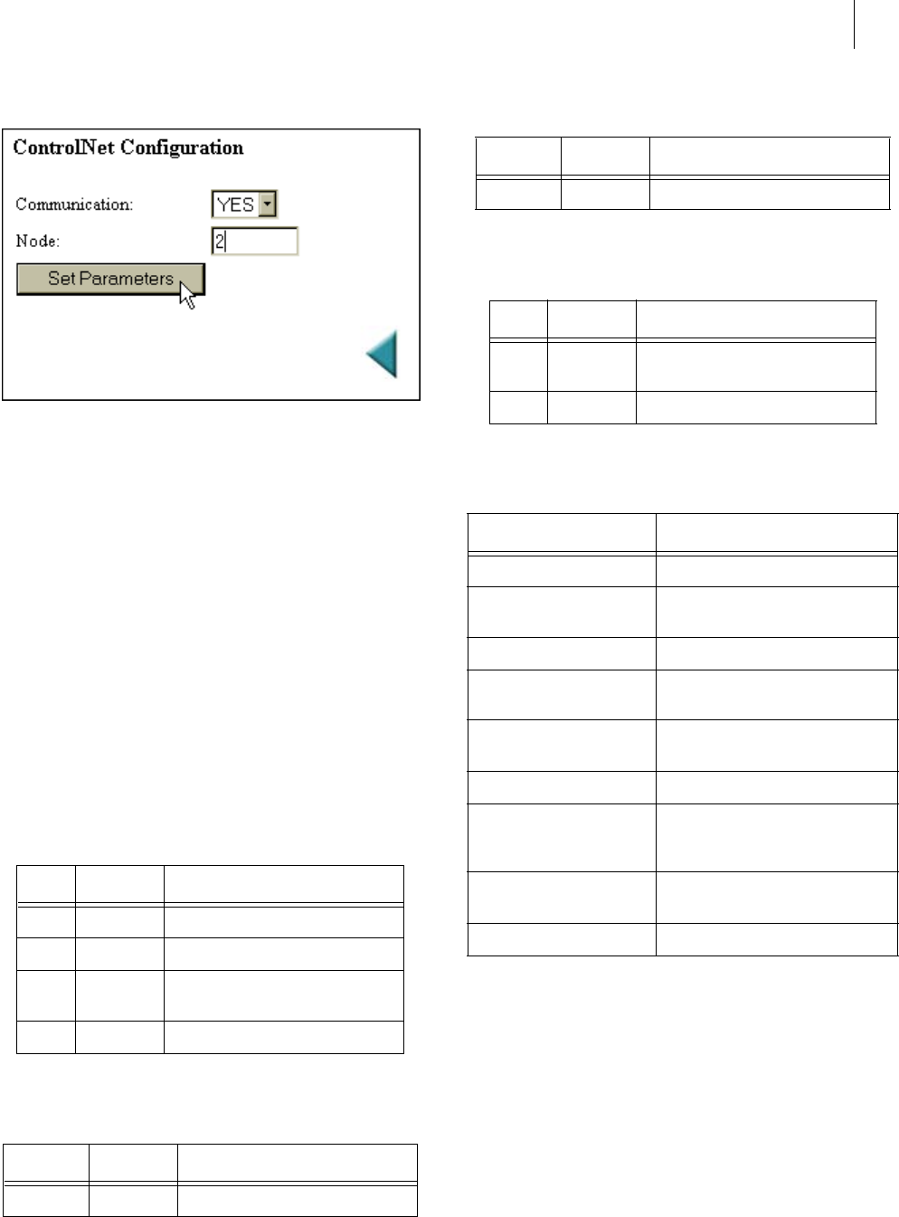
FIG. 62: CONTROLNET CONFIGURATION/ENTER-
ING NODE ADDRESS
Step 8. Click on the Set Parameters button to save the set-
tings.
Step 9. Click on the left arrow or the word “home” at the
bottom of the page to return to the Home Page.
LED Status Indicators
The ControlNet Card is fitted with four bi-color status and
indicator LED’s. (See Fig. 88) During startup the Module
Status (LED 1) and the Module Owned (LED 4) are red for
one (1) second to indicate they are working properly. After
the one second period they are lit as specified below in the
tables. After the module is initialized, the network LED’s
will flash red/green for one (1) second, indicating a self test
of the network chip.
For information on setting up the module using RSLogix
5000 and RSNetworx go to the Network Section of this man-
ual.
EtherNet/IP™ Option Card Installation
CAUTION: MAKE SURE THAT YOU USE AN ANTI-STATIC
STRAP WHEN INSTALLING THE ETHERNET/IP OPTION
C
ARD.
NOTE: The dip switches do not function. It is a good idea
to leave all of them in the OFF position. Should
you accidentally turn on a dip switch nothing will
happen. The IP address is configured by the firm-
Color Frequency Description
Green Flashing Module is waiting for initialisation
Green Steady on Module is initialized
Red Flashing Minor fault, MacID has been changed
after initialisation, etc.
Red Steady on Major fault, module must be restarted
TABLE 4: LED 1 - MODULE STATUS
Color Frequency Description
Red/Green - See Table 5
TABLE 5: LED 2 - LED CHANNEL A
Color Frequency Description
Red/Green - See Table 5
TABLE 6: LED 3 - LED CHANNEL B
Color Frequency Description
Green Steady on A connection is opened against the
ControlNet Module
Off - No connection is opened
TABLE 7: LED 4 - MODULE OWNED
Channel LED’s Description
A & B, steady off Module is not initialized
A & B, steady red Faulted unit, must be restarted or
repaired
A & B, alternating red/green Selftest of bus controller
A&B, flashing red Incorrect node configuration, dupli-
cate MacID, etc.
A or B, steady off Channel is disabled, depending on
network configuration
A or B, steady green Normal operation of channel
A or B, flashing green Temporary errors (node will self cor-
rect) or node is not configured to go
online
A or B, flashing red Media fault or no other nodes on the
network
A or B, flashing red/green Incorrect network configuration
TABLE 8: CHANNEL LED’S