
User Manual


125 CHAPTER 7
Troubleshooting
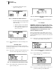
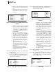
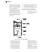
• If you Pass the Test the Pass display
appears. (See Fig. 7-86)
FIG. 7-86 RETURN TO ZERO TEST/PASS
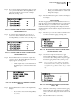
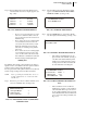
• If instrument Fails the test the Fail display
appears. (See Fig. 7-87) You may need to
do the following:
1. Check the scale for excess material.
2. Check your Motion and Zero Toler-
ance settings. They might be set too
low for your process.
FIG. 7-87 RETURN TO ZERO/FAIL
Step 4. Press the Exit button to return to the Diagnostics
display.
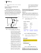
View Input States
The Input States display shows whether or not the instru-
ments has any inputs activated. A 1 means the input is active
and a 0 means it is not.
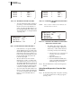
Step 1. Press the up or down arrow buttons until the cursor
is in front of View Input States. (See Fig. 7-88)
FIG. 7-88 DIAGNOSTICS/VIEW INPUT STATES
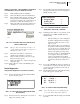
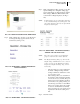
Step 2. Press the Enter button. The Input States display
appears. (See Fig. 7-89)
FIG. 7-89 INPUT STATES DISPLAY/INPUT 2 AND 4
ACTIVE
Step 3. Press the Exit button to return to the Diagnostics
display.
Force Outputs
WARNING: F
ORCING THE OUTPUT RELAY MAY CAUSE
DAMAGE OR PERSONAL INJURY. MAKE ABSOLUTELY SURE
THAT YOU KNOW WHAT THE RELAY IS CONNECTED TO
BEFORE ACTIVATING. IF INSECTARY DO A PHYSICAL CHECK
TO DETERMINE WHAT THE SELECTED RELAY IS CON-
NECTED TO BEFORE ACTIVATING.
The Force Outputs function individually activates each of
the 4 Output relays in the instrument. Useful in pre-startup to
determine that all the relays are connected to the correct aux-
iliary devices.
Step 1. Press the up or down arrow buttons until the cursor
is in front of Force Outputs. (See Fig. 7-90)
FIG. 7-90 DIAGNOSTICS DISPLAY/FORCE OUT-
PUTS
Step 2. Press the Enter button. A WARNING display
appears. (See Fig. 7-91)
FIG. 7-91 WARNING FOR FORCE OUTPUTS
Step 3. If you are not sure if this is what you want to do or
got here by mistake, press the Exit button.