
User Manual


HI-3010 Filler/Dispenser/IBC 12
Service Manual
• Always follow proper safety procedures
when working on or around the instru-
ment.
WARNING:
IF A LITHIUM BATTERY IS REPLACED WITH AN
INCORRECT TYPE IT MAY CAUSE AN EXPLOSION WHICH
WILL CAUSE PROPERTY DAMAGE OR PERSONAL INJURY.
Mechanical Installation
Installing the HI 3010 in a Panel
Panel Cutout Specifications
Enclosure Size Requirements:
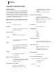
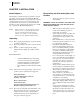
• Overall depth of the enclosure must be a
minimum of 8.5" to allow for the 2" clear-
ance between the rear panel of the HI 3010
Filler/Dispenser and the inside surface of the
rear panel of the enclosure. (See Fig. 3-1)
• There must be a 1" clearance completely
around the bezel and other installed units.
FIG. 3-1 REAR PANEL CLEARANCE REQUIRE-
MENT
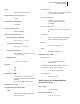
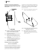
Dimensions of the panel cutout. (See Fig. 3-2)
• 8.94” ±.06 (227.076mm ± 1.52mm) Wide
• 6.625” ±.06 (168.26mm ± 1.52mm) High
FIG. 3-2 PANEL CUTOUT DIMENSIONS
Installing the HI 3010 Filler/Dispenser
Step 1. Make sure that all Electrostatic Discharge (ESD)
precautions are taken before and during installation.
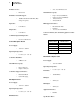
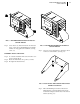
Step 2. The Filler/Dispenser comes with a NEMA 4 & 4X
rated compression gasket. Slide the gasket over the
rear of the instrument until the gasket is flush with
the back side of the front panel. (See Fig. 3-3)
FIG. 3-3 PANEL MOUNT INSTALLATION
Step 3. Gently slide the Filler/Dispenser with the gasket
into the cutout in the enclosure front panel or door
until the gasket is flush with the enclosure front
panel. (See Fig. 3-4) Be sure to secure the instru-
ment with both hands when installing.
Step 4. Line up the instrument’s tapped holes with the
through holes in the enclosure front panel.
8.94" (227.076)
6.625" (168.26)