
User Manual


HI-3010 Filler/Dispenser/IBC 18
Service Manual
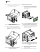
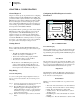
FIG. 3-17 DC POWER SUPPLY CONNECTION
Step 1. Connect your positive and negative DC voltage
lines to the Phoenix connector that plugs into the
DeviceNet Connector. (See Fig. 3-17)
Step 2. Plug the connector into the DeviceNet Connector at
the rear panel.
NOTE: Use DC power source when you have the -DC
option and do not have the DeviceNet Option.
The DeviceNet option has its own DC power
source.
Load Point Connections
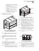
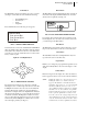
FIG. 3-18 REAR PANEL/LOAD POINT CONNEC-
TIONS
C2
®
Load Point Connection
Cable color Code for C2 Load Points (left to right facing the
rear panel):
• Shield Ground Wire
• C2- Violet
•C2+ Grey
•EXC- Black
•SEN- Brown
• SIG- White
• SIG+ Green
• SEN+ BLUE
•EXC+ RED
Step 1. Remove the factory installed jumper from the ter-
minal block if you are connecting an 8 wire cable
from the junction box.
Step 2. Connect the cable (Recommended load cell cable:
Hardy Instruments Prt. # 6020-0001) wires to the J9
terminal block according to the cable color chart.
(See Below)
NOTE: To purchase Hardy Load Cell cable, contact your
local Hardy Representative or Distributor.
Step 3. Plug the terminal block into the Channel 1 connec-
tor on the rear panel.
Non-C2 Load Point Connection
Cable color Code for Non-C2 Load Points:
• Shield Ground Wire
• C2- Not Used
• C2+ Not Used
• EXC- Black
•SEN- Brown
• SIG- White
• SIG+ Green
•SEN+ Blue
•EXC+ Red
Step 1. Remove the factory installed jumper from the ter-
minal block if you have 6 wire load cell cable that
includes sense wires from the load cell or junction
box.
Step 2. Connect the cable (Recommended load cell cable:
Hardy Instruments Prt. # 6020-0001) wires to the J9
terminal block according to the Non-C2 cable color
chart.
Step 3. Plug the terminal block into the Channel 1 (J9) con-
nector on the rear panel.
LVDT and Half Bridge Load Cells/Sensors
Please contact Hardy Technical Support for installation
instructions.
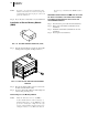
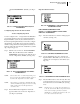
Junction Box Wiring
FIG. 3-19 JUNCTION BOX CONNECTIONS
Step 4. Connect the cable wires directly to the terminal
blocks according to the C2 or Non-C2 cable color
charts.
Step 5. Plug the terminal blocks into Channels 1 thru 4 con-
nectors on the rear panel. Write down which load
cell is connected to Channel 1, Channel 2, Channel
3, Channel 4 for future reference.