
User Manual


77 CHAPTER 6
Mapping
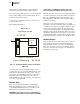
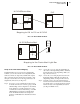
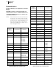
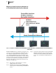
FIG. 6-42 HARDY CONTROL LINK NETWORK MAPPING
Boolean Mapping
A Boolean variable is a variable that can have the value 0
(FALSE) or 1 (TRUE). In the HI 3010 Filler/Dispenser there
are 3 boolean operations supported:
• AND - The symbol for “AND” in a Bool-
ean Assignment Statement is “*”.
• OR - The symbol for “OR” in a Boolean
Assignment Statement is “+”.
• NOT - the symbol for “NOT” in a Boolean
Assignment Statement is “~”.
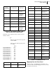
The Boolean image tables are arrays of short (2 byte) inte-
gers. An individual Boolean variable in the image table is
located by its word offset and its bit offset. Boolean image
tables are given 2 letter names as follows:
• DI is the DeviceNet input image table.
• DO is the DeviceNet output image
table.
• HI is the Hardy input image table.
• HO is the Hardy output image table.
• RI is RIO input image table.
• RO is RIO output image table.
The RIO input and output images tables are mapped to phys-
ical external devices using RSLogix. DeviceNet and Con-
trolNet input and output image tables are mapped to physical
external devices using Rockwell Software’s RS NetWorx.
The Hardy input and output image tables have pre-defined
meanings for certain bits within the tables.
NOTE: Make sure you use RS NetWorx for DeviceNet
and RS NetWorx for ControlNet. They are two
different applications.
A Boolean variable is addressed with the syntax below:
[tablename][word offset].[bit offset]
Example:
DI0.3 is bit #3 in the DeviceNet input table, word #0.
Analog Mapping
An analog variable is one that can have many different val-
ues. The HI 3010 Filler/Dispenser supports float, 16 bit inte-
ger, and 32 bit integer analog variable types.
There are three (3) analog operations supported. The sym-
bols are the same as the Boolean operations, but with differ-
ent meanings.
• Multiply - The symbol for “Multiply” is
“*”.
• Add - The symbol for “Add” is “+”.
• Negate - the symbol for “Negate” is “~”.
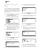
Analog tables are given 3 letter names as follows:
DFI, DFO, DSI, DSO, DII, DIO all refer to DeviceNet
tables, where the item is a float, a short integer, or a 32 bit
integer depending on the second letter in the table name. HFI
is a table of Hardy defined floating point numbers.
An analog variable is addressed with the syntax below:
[tablename][word offset]
The offset is an offset in words in the case of the DeviceNet
tables. The offsets in Hardy tables have various predefined
meanings.
• HFI0 - is Gross Weight
• HFI1 - is Net Weight
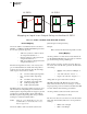
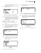
Mapping an Input to an Output Relay on Another HI 3010
HI 3010
Input Image
Table
Output Image
Table
Node #1
Input Contact #1
HI 3010
Input Image
Table
Output Image
Table
Node #2
0
1
2
3
Output
Hardy Boolean Out
Output Relay #3
From Sensor
0
1
2
3
4
Input
Hardy Boolean In
Too Actuator