
User guide

Load Point Installation
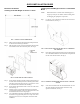
FIG. 5 REAR PANEL/4 LOAD POINT CONNECTIONS
C2
®
Load Point Connection
WARNING: LOAD CELL CABLE LENGTH HAS BEEN CALCU-
LATED INTO C2 CALIBRATION DATA. HARDY RECOMMENDS
THAT YOU DO NOT CUT YOUR ADVANTAGE OR ADVANTAGE
LITE LOAD SENSOR CABLE, AS YOUR C2 ACCURACY WILL BE
AFFECTED AND THE WARRANTY WILL BE VOIDED.
Cable color Code for C2 Load Points (left to right facing the rear panel):
• Shield Ground Wire
• C2- Violet
• C2+ Grey
• EXC- Black
• SEN- Brown
• SIG- White
• SIG+ Green
• SEN+ BLUE
• EXC+ RED
Step 1. Remove the factory installed jumper from the terminal block if
you are connecting an 8 wire cable from the junction box.
Step 2. Connect the cable (Recommended load cell cable: Hardy
Instruments Prt. # 6020-0001) wires to the Channel terminal
block according to the cable color chart.
Step 3. Plug the terminal block into the Channel connector on the rear panel.
Step 4. For more information concerning C2 Load Point connection,
consult the HI 3000 Series Installation and Service Manual.
Non-C2 Load Point Connection
NOTE: Cable Color Codes vary between vendors, check with you
supplier for the Color Code for your Non-C2 load point.
Step 1. Remove the factory installed jumper from the terminal block if
you have 6 wire load cell cable that includes sense wires from
the load cell or junction box.
Step 2.
Connect the cable (Recommended load cell cable: Hardy Prt. #
6020-0001) wires to the Channel 1 terminal block according to
the Non-C2 cable color chart, or per manufacturers specification
.
Step 3. Plug the terminal block into the Channel connector on the rear panel.
AC Input Power Wiring
WARNING: DO NOT OPERATE WITH INCORRECT LINE VOLT-
AGE. TO DO SO WILL RESULT IN PROPERTY DAMAGE AND/OR
PERSONAL INJURY. MAKE SURE THAT THE POWER SOURCE
DOES NOT EXCEED 240 VAC.
NOTE: For DC Input Power Wiring See the HI 3030 Weight Con-
troller Installation and Service Manual.
• The AC power should be supplied by a “clean” pri-
mary line, directly from the power panel. This line
should not supply any other equipment, including
the feeding unit, and should be supplied with a mini-
mum 10 amp breaker. (See Fig. 7)
FIG. 6 POWER WIRING DIAGRAM
• Power Input J1
J1-1 Net (Low)
J1-2 Line (HI)
J1-3 Ground
Step 1. The HI 3000 Series instruments are configured with a univer-
sal power supply rated from 120 to 240 VAC.
Step 2. Install a 3-wire, minimum 14 AWG power line to the 3-pin ter-
minal block connector.
Step 3. The Instrument boots up to the Summary Screen which will
display 1, 2 or 4 Channels. (See Figs. 7 & 8)
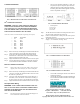
FIG. 7 SUMMARY DISPLAY/2 CHANNELS
FIG. 8 SUMMARY DISPLAY/4 CHANNELS
• Go to the HI 3030 Weight Controller User Guide for
operating instructions.
• Go to the HI 3030 Weight Controller Installation and
Service Manual for further Installation and Configu-
ration Instructions.
9440 Carroll Park Drive, San Diego, CA 92121
Telephone: 1-800-821-5831 FAX: (858) 278-6700
Web Address: http://www.hardysolutions.com
Hardy Document Number: 0596-0264-01 REV E
Copyright 2011, Hardy Process Solutions. Printed in the U.S.A.