
User guide


148
Appendix A
•
•
•
•
•
•
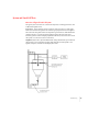
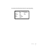
The 32-bit
Aux Command Information i
s used for specific information required for
special commands. To select which parameter is being read or written, set the predefined
number into the
Parameter ID
. If the value is being read, then the
Parameter Value
is
ignored, or set to the required value if the value is being written.
The next 3 values,
Reserved 1
,
Reserved 2
, and
Reserved 3
, are reserved, and also provide
padding so the user selectable read only parameters are aligned between the output and
input tables. The next 5 values Parameter
RD1
ID
,
Parameter RD2 ID
,
Parameter RD3
ID
,
Parameter RD4 ID
, and
Parameter RD5 ID
are user selectable parameter ID values
which are used to return read only values from the instrument. These read only values can
be anything from an instrument specific measurement such as COUNT to a parameter value
such as WAVERSAVER.
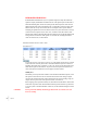
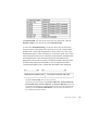
INPUT Table Description
The first four variables in the input table,
Command Echo
,
Command Status
,
Parameter
ID
, and
Parameter Value
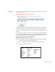
, closely match the first four variables in the output table. The
Command Echo
is used to echo the command from the output table, to enable the PLC to
ensure that the correct command has been executed; and also that command has been
completed and the command status value is valid. The response of the instrument to the
generic command value or the read only parameter command values, is provided in the
Command Status
value, and verifies if the command was executed with the expected
result.
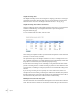
The top 8 bits are reserved for indicating if the
Parameter RDx ID
commands were
executed correctly. If the bit is HIGH then either the
Parameter ID
is invalid or the value
returned is invalid. When this occurs, sending the command using the
Command
,
Aux
Command
Information
,
Parameter ID
, and
Parameter Value
in the output table will
provide the required information to debug the problem.