Weight Processor HI 6500 Series User’s Guide Hardy Process Solutions Document Number: 0596-0331-01 REV C
Local Field Service Hardy has over 200 field technicians in the U.S., and more positioned throughout the world to assist you in your support needs. We also have factory engineers who will travel to your facility anywhere in the world to help you solve challenging applications.
Contents •••••• Chapter 1 HI 6500 Overview - - - - - - - - - - - - - - - - - - - - - - - - - - - - - 1 General Introduction to the HI 6500 Series Weight Processor - - - - - - - - - - 1 HI 6500 Series Weight Processor Description- - - - - - - - - - - - - - - - - - 1 Typical Applications - - - - - - - - - - - - - - - - - - - - - - - - - - - 2 Features and Capabilities - - - - - - - - - - - - - - - - - - - - - - - - - - - 2 Hardy Process Toolbox- - - - - C2® and eCal™ Calibration - - INTEGRATED TECHNICIAN® W
Load Cell Wiring Diagrams - - - - - - - - - - - - - - - - - - - - - - - - - - 24 Connecting to a Hardy Junction Box or Summing Card - - - - - - - - - - 25 Chapter 4 Network Configuration- - - - - - - - - - - - - - - - - - - - - - - - - - - 27 Ethernet TCP/IP Network Configuration - - - - - - - - - - - - - - - - - - - - 27 LAN Connection - - - - - - - - - - - - - - - - - - - - - - - - - - - - - - - 28 DHCP Configuration Using the Front Panel - - - - - - - - - - Direct Connect Hardware - - - - - - - - - - -
Front Panel Display - - - - - - - - - - - - - - - - - - - - - - - - - The Five Button Command Cluster - - - - - - - - - - - - - - - - - - Using the Mode, Zero, and Tare buttons - - - - - - - - - - - - - - - - Entering Numeric and Alphanumeric Values - - - - - - - - - Commands and Parameters - - - - - - - - - - - - - - - - - - - - - - Calibration Menu - - - - - - - - - - - - - - - - - - - - - - - - - - C2 (eCal) Commands and Parameters - - - - - - - - - - - - - Ref Weight Parameter - - - - - - - - - - - - -
WAVERSAVER® ParameterInformation Page- - - - - - - - - Language Parameter Menu - - - - Operations Parameter Menu - - - - - - - Chapter 6 - 90 91 91 92 Tare Operations Commands and Parameters - - - - - - - - - - - - - - - Tare Amount Parameter - - - - - - - - - - - - - - - - - - - - Tare Offset Parameter - - - - - - - - - - - - - - - - - - - - - Tare Command - - - - - - - - - - - - - - - - - - - - - - - - Zero Operations Commands and Parameters - - - - - - - - - - - - - - - Zero Tolerance Parameter - - -
Electrical Check Procedures - - - - - - - - - - - - - - - - - - - - - - - - - - 110 Load Cell/Point Input/Output Measurements - - - - - - - - - - - - - - - 110 Load Check - - - - - - - - - - - - - - - - - - - - - - - - - - - - - - - 111 C2 & eCAL Electronic Calibration- - - - - - - - - - - - - - - - - - - - - - - 111 Gravitation Correction - - - - - - - - - - C2 and eCAL Calibration from the Web Page C2 Calibration from the Front Panel- - - - Hard Calibration - - - - - - - - - - - - - - - - - - - - -
Weight - - - - - - - - - - - RTZ (Return to Zero) Test - - - - - IT Test - - - - - - - - - - - - - - Sensor Number - - - - - - - General Troubleshooting Flow Chart Index- - - - - - - - - - - - - - - - - - - - - - - - - - - - - - - - - - - - - - - - - - - - - - - - - - - - - - - - - - - - - 142 143 143 143 145 A - Guideline Instability: Electrical and Mechanical review.- - - - - - - - - - - 146 A1. Checking for Unstable Components in a Weighing System - - - - - - - - - 147 B.
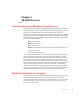
Chapter 1 HI 6500 Overview •••••• General Introduction to the HI 6500 Series Weight Processor This Manual describes installation, setup and troubleshooting procedures for the HI 6500 Series Weight Processor. Be sure to read and understand all cautions, warnings, and safety procedures in this manual to ensure safe operation and repair of this instrument. Hardy Process Solutions sincerely appreciates your business. We encourage input about the performance and operation of our products from our customers.
The HI 6500 series can be used with or without a display. The display is a bright 4.3” high-contrast LCD capable of high-resolution graphics and discrete messaging. The unit can be panel mounted, DIN mounted, and remote display mounted. The thin enclosure and low power consumption allows for high density control cabinet design.
WAVERSAVER® When measuring small weight changes, the effects of mechanical vibration and noise from feeders and other plant environmental conditions can introduce substantial interference. WAVERSAVER factors out vibration, noise, and other interference-related signals from the load cell so the weight processor can better decipher the actual weight data. WAVERSAVER can factor out noise with frequencies as low as 0.25 Hz or as high as 7.5 Hz.
4 • • • • • • Chapter 1
Chapter 2 Specifications •••••• Chapter 2 provides specifications for HI 6500 series instruments. The specifications listed are designed to assist in the installation, operation and troubleshooting of your instrument. All service personnel should be familiar with this section before installing or repairing the instrument.
Non-linearity • 0.0015% of full scale Common Mode Rejection • 110dB at or below 60 Hz Common Mode Voltage Range • 2.5 VDC maximum (with respect to earth ground) Front Panel (optional) • Monochrome 480 x 272 LCD display with back light • Five tactile keys for menu item selection • Displays in either white on black or black on white Load Cell Excitation • 5 VDC +/- 1.
Temperature Coefficient • Less than 0.005% of full scale per degree C for Cal-LO and Cal-HI reference points Storage Temperature Range -40 to 85º C (-40º to 185º F) Humidity Range • 0-90% (non-condensing) Environmental • Intended for Building In, indoor use only at ambient temperatures between 10ºC to 60º C (14º to 140º F) with a pollution degree of 2.
8 • • • • • • Chapter 2
Chapter 3 HI 6500 Installation •••••• Chapter 3 covers unpacking, cabling, interconnecting, configuring, and installing the HI 6500 series of instruments. User and service personnel should read this chapter before installing or operating the weighing functions of the instrument. WARNING - EXPLOSION HAZARD - SUBSTITUTION OF COMPONENTS MAY IMPAIR SUITABILITY FOR DIVISION 2.
Step 5. Be sure to complete the warranty registration on the Hardy Process Solutions web site. Spare Parts List Part Reference HI 6110 0551-0653-01-0 0578-0072-01 0524-0034-01-0 2140-0092-0 2140-0139-09-0 2140-0139-06-0 2140-0139-03-0 0509-0534-01-0 Description HI 6500 Series Instrument Display (Optional) HI 6500 Series Alt.
• Do not install the instrument right next to an AC power source or high voltage DC • equipment Route all the low voltage cables away from high voltage cables. Installation options for the HI 6500 series instrument The HI 6500 series instrument can be mounted in four different configurations. There are two panel mount options, one DIN rail mount option, and a wall mount option.
Mounting the Front Panel Display Step 1. Make sure that all Electrostatic Discharge (ESD) precautions are taken before and during installation. Step 2. A thin plastic template comes with the product. Make the hole pattern in the panel door or cover using the dimensions provided on the diagrams below. Panel Hole Dimensions (not displayed to scale) A printable template is available on the Hardy website. Printers and copy machines can distort or reduce the template measurements shown above.
Panel Mount Option 1 FIG. 1 Exploded View of the Panel Mount Assembly – Option 1 with optional mounting kit Step 1. Screw the Panel Mounting Brackets to the top of the enclosure Step 2. Connect and hand tighten the four screw rods into the front panel display Step 3. Push the screw rods and cable assembly though the holes in the panel. Step 4. Connect the front panel display cable assembly Step 5. Tighten the four 4mm nuts enough to completely compress the gasket for IP65 Step 6.
Finished Panel Mount Assembly – Option 1 Panel Mount Option 2 Exploded View of the Panel Mount Assembly – Option 2 NOTE No brackets are needed for this installation. Step 1. Connect and hand tighten the four screw rods into the front panel display Step 2. Connect the front panel display cable assembly Step 3. Push the screw rods and cable assembly though the holes in the panel.
Step 4. Secure display to panel using four 4mm nuts and washers on the screw rods. Step 5. Tighten the four 4mm nuts enough to completely compress the gasket for IP65 compliance. Step 6. Position the enclosure with the connectors pointing downwards Step 7. Align the screw rods with the holes in the enclosure Step 8. Connect the cable assembly Step 9. Slide the enclosure onto the screw rods until flush with the panel Step 10.
• Use three twisted pairs with a drain wires • Pair wires +12 and GND, D1 and D2, D3, and D4 View from the rear of the front display panel The terminal type is a spring cage type contact. There is a slot provided to use an insert/release tool. The tool is a 2.0 mm x 0.4 mm wide flat blade screw driver. Inserting the tool opens the cage contact and allows one or two bare wires to be inserted. Removing the insertion tool with bare conductor inserted will lock the connection.
View from the front of the instrument showing the display connector. DIN Rail Mount Exploded View of the DIN Rail Mount Assembly NOTE The DIN Rail mount can be used with a remote display or operated as a Blind unit Step 1. Pull down the DIN rail clip to expose the DIN Rail bracket. Do not fully remove the clip from the housing. Step 2. Hook DIN rail bracket onto the DIN rail using the groove at the top of the bracket Step 3. Push the DIN rail clip up until it locks in place.
Step 4. While holding the HI 6500 series instrument, gently pull the bottom of the HI 6500 away from the DIN rail to verify that it is mounted correctly. Completed DIN Rail Mount Assembly Wall Mount Wall Mount Assembly exploded from the front with optional mounting kit To wall mount the HI 6500 series instrument, the display and weight processor need to be assembled; then the assembled instrument can be mounted onto the wall. Step 1.
Step 1. Attach the mounting brackets using the supplied brackets and screws Exploded View of the Wall Mount Assembly – Rear View Step 2. Place the assembled wall mounted unit against the wall Step 3. Mark the centers of the wall mounting brackets Step 4. Drill and insert the required wall plugs if attaching to brick, concrete, or plaster board. If attaching to wood use a pilot drill to ensure alignment. Step 5.
Completed Wall Mount Assembly Remote Display Mount Exploded View of the Remote Display Mount Assembly The display for the HI 6500 series instrument can be mounted in a remote location and the supplied cable can be modified to support the desired length of cable (not supplied). Step 1.
Step 2. Disable the cable assembly provided, and replace the original cable with the desired cable length (not provided--up to 100 ft (30.48 meters)). Build the cable assembly using the instructions above for Making Longer Display Interface Cables on page 13. Step 3. Connect the front panel to the newly assembled display cable Step 4. Push the screw rods and cable assembly though the holes in the gasket. Step 5. Slide the screw rods through the panel until flush with the surface Step 6.
DC Power Input WARNING - Do not operate with incorrect line voltage. To do so will result in property damage and/or personal injury. Make sure that the power source does not exceed 24 VDC. AVERTISSEMENT – Assurez-vous que la source d’alimentation ne dépasse pas 240 V. L’utilisation d’un mauvaise voltage peut résulter en dégâts matériels et/ou des risques de blessures. WARNING - Be careful not to reverse the ground and hot wires, which can result in damage to the equipment.
WARNING - If the HI 6500 series equipment is used in a manner that is not specified by the manufacturer, the protection provided by the equipment may be impaired. AVERTISSEMENT – Si l'équipement de série HI 6500 est utilisé d'une façon qui n'est pas spécifiée par le fabricant, la protection fournie par l'équipement peut être altérée. Disassembly and Reassembly Notes and Cautions • Installation of this equipment must comply with International, National and Local Electrical and Mechanical codes.
Load Cell Wiring Diagrams The diagrams below show how Hardy Load Sensor with C2 wiring differs from standard Load Cell (4 wire and 6 wire are similar except 6 wire adds sense wiring. C2 wiring is required when using a Integrated Technician summing junction box. The C2 wires are used for communicating IT and C2 commands. Industry standard load cells wiring Hardy load sensor C2 wiring The simple wiring diagram above shows how to connect a single load cell to the HI 6500 series instrument.
Connecting to a Hardy Junction Box or Summing Card Junction Box Wiring Diagram NOTE When connecting two IT Junction Boxes together to connect 8 load points, you must run an external 5 Volt DC power supply if you will run C2 cabling a long distance. You cannot use a higher voltage power supply due to over voltage damage to your Hardy controller. For more information, visit the Hardy Knowledgebase Answer #1370 or search under external excitation voltage.
HI 6010 Summing Card Diagram NOTE • • 26 •• • • Chapter 3 When connecting a Hardy Summing Box to the HI 6500, you must remove the two factory installed jumpers on pins 1 & 2 and on pins 5 & 6 on the module and install C2 and sense wires. C2 wires carry the commands for Integrated Technician and the C2 calibration information.
Chapter 4 Network Configuration •••••• Chapter Four contains step-by-step instructions for configuring Hardy HI 6500 series instruments and related communication networks. We recommend reading these procedures because having a correct configuration is necessary to ensure trouble-free operation.
LAN Connection To connect the HI 6500 series instrument to a LAN, you simply connect a standard Ethernet cable between the instrument and the common network hub. You will then need to determine which scheme is used on the network to assign IP addresses. Every node on the network must have a unique IP address or conflicts will result. Contact your Network Administrator for the IP address to use for the instrument.
Fixed IP Configuration Using the Front Panel The HI 6500 series instrument can be configured to use any Fixed IP address. The Fixed IP addresses must be carefully selected to avoid accidentally configuring two devices to the same address with unpredictable results. Since ‘guessing’ a value could lead to personal or property damage and/or interrupted network services, your network administrator should provide this address. Read-only screens can display a limited number of characters per line.
Step 3. Starting at the right-most digit, enter the IP number using the standard format. Use the up/down arrows to select each character, and press the left arrow to move to the next digit. Step 4. Press Enter to save the entry. Step 5. Press the Exit key four times to exit the IP, Ethernet, communications and configuration menus. The IP address is now saved and the instrument’s embedded Web browser is now available at the entered IP address.
Windows XP Step 1. After starting your computer, click Start.and then Control Panel. Step 2. Click on Settings > Network Connections. Step 3. Right click on ‘Local Area Connection’ and select Properties. Step 4. Click on Internet Protocol (TCP/IP) and click on the Properties button to open the Internet Properties (TCP/IP) Properties dialog. Step 5.
Step 11. Select OK in the TCP/IP Properties dialog box. The computer is now fully configured. Step 12. To return the computer to the original network settings, return to the Internet Properties (TCP/IP) dialog , select ‘Obtain an IP address automatically,’ and click OK. Direct Connect Configuration - HI 6500 Series Instrument The HI 6500 must now be assigned a unique IP address that will connect to the Windows PC.
I/O Tables For Communications to PLCs The following I/O table description is common for the following communication protocols 1 2 3 4 EtherNet/IP Modbus-TCP Modbus-RTU Profibus-DP For a full list of command parameters, please see the “Default Parameter IDs and Values” on page 106 at the end of Chapter 5.
The 32-bit Aux Command Information is used for specific information required for special commands. To select which parameter is being read or written, set the predefined number into the Parameter ID. If the value is being read, then the Parameter Value is ignored, or set to the required value if the value is being written.
A 32-bit value, Instrument Status, provides the current state of all the major functions within the instrument. The top 8 bits are a cyclic “measurement update count”, which will increment by a count of one every time a new measurement value is taken, following a 0 to 255 then repeat cycle. If this value remains the same in two consecutive reads from the instrument then the communication or the measurement function has failed and the appropriate action needs to be taken.
• 0: READ PARAM CMD. To read a parameter, write a #0 to the command register • • • (register #0), and write the parameter number in the parameter ID number in registers 2 and 3, most significant word first. The parameter value may then be read from registers 4 and 5, again most significant word first. This value may be in integer or floating point format, depending on the parameter. The status register in the reply will contain the lower 16 bits of the system status word.
Calibration_Fail 1 Calibration_Fail_Motion 3 Calibration_Fail_Adc_Error 4 Calibration_Fail_Noc2 5 Calibration_Fail_C2capeq 6 •alibration_Fail_C2clones 7 0x1000 (4096 decimal): WRITE INTEGER CMD. Set the value of an integer parameter. Write 0x1000 in the command register 0, the parameter ID number in registers 2, 3 and the desired value in registers 4, 5. • No Error Codes • • • • • • • • 0x1001 (4097 decimal): WRITE FLOAT CMD. Set the value of a floating point parameter.
If there is a problem with the connection between the PLC and the HI 6500, recheck the IP addresses used and the setup parameters in the PLC I/O configuration. The read-only Connected entry confirms that the 6500 is connected to the network. If the instrument is not connected to the network, a message appears saying “Not Connected.” Check the EtherNet/IP connection at the rear of the instrument to make sure it is securely fastened to the EtherNet/IP port.
Step 1. Click the Hardy Modbus-Link icon to open the Hardy Modbus-Link display. Step 2. Click Connect n the Connection pull-down menu, to display the TCP/IP Connection form. Step 3. If TCP/IP is not selected, select it from the pull-down list. Step 4. Step 4. Type the address of the HI 6500 module you want to communicate with into the IP Address text box and click OK.
The red “No Connection” disappears and the values at the top of the page start to change. You are now connected from your PC to the HI 6500 weight processor. Step 5. Step 5. On the Setup pull down menu select Poll Definition and select the function 04 INPUT REGISTER and the Adress 0 and Length as 24.. Step 6. On the Hardy Modbus-Link page. Display pull-down menu, select Float Inverse. The Weight value would be found in register 5 (net) or 6 (gross).
Step 7. From the DISPLAY drop down, select the Long Inverse selection. This will allow us to write an integer value into the non-float registers. Step 8. From the FUNCTION drop down list select Read/Write registers, or click button 23 to open the Write multiple registers display. Step 9. Double click on the first register and the Enter Value box appears. Enter the new value you wish to write to this register. Our example shows writing a value of “2”, which is the Tare command number.
Step 10. Click on OK to accept the value and click on the Send button to send it to the HI 6500. Click OK to the Response OK message. Step 11.
Modbus-RTU (over RS-485) Step 1. Setup a slave address assigned to the HI 6500 series instrument from the communications menu and the Modbus-RTU submenu.. Use a unique address between 1 and 247 Step 2. Set the Baud Rate to the same as the master device, typically 9600 or 19,200 Step 3.
• Registers 4, 5: parameter value The Modbus master sends a 'command' by writing a value to register 0. Any non-zero return value is an error. Here is a list of Hardy command numbers: • 0: READ PARAM CMD. To read a parameter, write a #0 to the command register (register #0), and write the parameter number in the parameter ID number in registers 2 and 3, most significant word first. The parameter value may then be read from registers 4 and 5, again most significant word first.
Calibration_Fail_Adc_Error 4 • • 0x65 (101decimal): CAL HIGH CMD. Write a 0x65 hex to the command register to perform the high step of a traditional calibration. • Calibration_Fail 1 • Calibration_Fail_Motion 3 • Calibration_Fail_Adc_Error 4 • HardcalFailCounts 8: not enough counts between hard cal hi and hard cal lo • 0x66 (102 decimal): C2 CAL CMD. Write a 0x66 hex to the command register to perform a C2 calibration.
2. Enter the command #0 into data register #0. 3. Run the Modbus Function code #16 (write multiple registers). 4. Run the Modbus Function code #4 (read multiple registers). 5. Read the value for the span parameter in data registers #4 & 5. This value will be in floating point format. Example 2: If you wish to write a new span value of 100.55: 1. Enter the Span parameter ID into data registers 2 & 3. The Span ID is 0x0000 0201. 2. 3. a. Place 0x0000 into data register #2. b.
Profibus-DP The Profibus®-DP (Decentralized Peripherals) communication profile is designed for efficient field-level data exchange. Central automation devices, such as PLC/PC or process control systems, communicate through a fast serial (RS-485) connection with distributed field devices, e.g. PLCs. To begin communicating weighing parameters between an HI 6000 Series controller and a PLC, PC or DCS system controller, you need only to load the *.GSD file and set the node address.
Configuring PROFIBUS From the Web Interface Step 1. Step 1. From the Configuration menu select Options to open the Options menu; then Click on Profibus Card. to open then Click on Profibus Card form. Double click in the Node text field to highlight the current entry. Type in the HI 6500 OR HI 6510 Node address. Range:1-125 (default 5) Our example uses the default address #5. NOTE Profibus Node Address #5 is the lowest number that can be used by a slave device. Step 2.
Profibus-DP .GSD File All devices connected to a Profibus-DP network require a *.gsd file. The *.gsd file contains all the parameters including the baud rate, table formats and necessary data required by the network PLC when an HI 6500 or HI 6510 is connected to the network. You must download the proper *.GSD file from the Hardy website. Step 1. Navigate from the products section to the HI 6500 web page. Step 2. Click on the Tab, Docs & Programs and scroll down to Documents and Programs. Select the *.
Step 5. Install the *.GSD file for the instrument you connected to the Profibus Network. Configuring Profibus from the Front Panel Step 1. Press the Configuration key Step 2. Down arrow to Communications; press enter. Step 3. Select Profibus-DP; press enter. Step 4. Select Termination; press enter Step 5. Up or down arrow to make termination selection. Press enter to select. Step 6. Down arrow to select Serial Option; Step 7. Press enter to toggle between Profibus-DP and Modbus.
Step 3. Click + to expand the General Folder. Step 4. Highlight the CPU you selected in the UR dialog box.
Step 5. Double Click on “HI6000” or drag and drop the “HI6000” folder to the ProfibusDP Network. This opens the HI 6000 PDP Parameters dialog box where you can set the address of the instrument, if necessary. Step 6. Click OK to set the Node Address. Step 7. The HI 6500 Series module appears in the Profibus Network.
Step 8. Click in the module properties at slot 1. In the catalog, expand the module properties and make selection for "48 bytes in and out". Step 9. Once the selection has been made, you should see the input and output words showing the associated addresses in the table as shown.
NOTE The HI 6500 or HI 6510 Series Input and Output Sizes are expressed in 32 bit words. 12 words input and 12 words output. Step 10. Click the Download Icon to download the configuration to the PLC and open the Select Destination Module dialog box. Step 11. Click OK to open the Select Station Address Dialog box; then click OK again. A status box will show the progress of configuration download to the PLC. Step 12. When the download is complete the HW Config dialog box should look something like this.
Printer (over RS-232) The HI 6500 series can transmit Gross, Net, Count, Tare values to a serial printer over RS232. The printer Baud rate is user selectable at 600, 1200, 2400, 4800, 9600, or 19200 (default is 9600). The RS-232 printer pinout is: GND DNC TR+ TRPrtRX PrtTX Signal DO Not RS485 Pins Not Used Printer RX Printer TX Ground Connect A sample wiring connection from the HI 6500 seri3esto the printer port is shown above.
Step 1. Insert the USB stick into the HI 6500 series instrument Step 2. Using the web interface or display panel, save or restore system parameters. Communications Parameters for the HI 6510 Only Analog 4-20mA Available on the HI6510 only The analog 4-20mA output is directly proportional to the programmed gross, net, or count range; by setting the low value equal to 4mA and the high value equal to 20mA. These values can be set from either the front panel or the web interface.
Step 3. Set he 20mA value Step 4. Save Parameters NOTE Setting the weigh source to manual allows the A output setting to be set to a fixed output. This is used to test the circuit level to the host. If not operating in manual mode, this would should the current mA output level.
• • 58 •• • • Chapter 4
Chapter 5 Instrument Configuration •••••• Using the Home Page to set Parameters Enter your HI 6500 series home page by typing the IP Address you used to set up the instrument (see Chapter 4 for information on setting the IP Address) accessing the instrument via a direct connection on a PC. From the Home Page, click Configuration to open the Configuration page. Select Instrument Setup to open the Instrument Setup page.
Using the Front Panel Display Menus to Set Parameters Front Panel Display The Front Panel Display is a 480 x 272 LCD graphical display. The Summary screen displays the current weight in the selected mode (Gross, Net or Count) and the selected engineering units (oz, lb, t (ton), g, kg, mt (Metric Ton)).
TARE Command Button When the TARE button is pressed the NET weight value is set to zero. ZERO Command Button When the ZERO button is pressed the GROSS weight value is set to zero. MODE Command Button The MODE button toggles the weight displayed between GROSS, NET. & Count. • Count is included if this mode is enabled CONFIG (Configuration) Command Button The CONFIG button minimizes the displayed weight value and provides a submenu structure on the screen which is navigated by the button cluster.
The CONFIG Menu Structure To configure and setup the HI 6500 series instrument press the CONFIG button. To enable you to continue to monitor the weighing process, the display for the the weight, mode, and zero symbol are reduced in size and placed in the top right hand corner. A submenu list is provided on the left hand side, with the current item that you have selected highlighted and identified by the ♦ symbol.
The UP and DOWN arrows are used to change the displayed digit. 0→1→2→3→4→5→6→7→8→9→.→ →0 The UP button increments from 0 through 9, then the decimal point, space, and back to 0, while the DOWN button decrements from 9 through 0, then the space, decimal point and back to 9. Example 4: 12345.01 Example 5: 02345.01 Example 6: 2345.01 In example 4, the LEFT button is used to select the 10000 value, in example 5 the DOWN button is used to decrement the value to 0.
Commands and Parameters The instrument commands and parameters are grouped into 10 categories: Calibration = Cal Communication = Comm Diagnostics = Diag Display (only active for units with a front panel display) = Display Filter = Filter Information = Info Language = Language Operations = Op Security = Security Setup = Setup These 10 categories are further broken down into sets of commands and parameters as shown in the following figure.
Calibration Menu • C2 eCAL o o o o o o Sensitivity Gravity Ref Wt Do C2 Calibration Cal Tol Num Dev • Hard Cal o o o o o o Cal Tol Sensitivity Cal Lo Wt Do Cal Lo Span Wt Do Cal Hi • Cal Date C2 (eCal) Commands and Parameters Cal Tolerance Parameter Sometimes, the contents of the vessel you are weighing are in motion. Cal Tolerance allows you to set a value that determines the amount of motion that the system can tolerate and still calibrate.
On the Web page, enter the value in the text box provided. On the HI 6500 series instrument display, select the calibration menu and use the UP or DOWN button to select the C2 (eCAL) submenu, then select the Cal Tolerance (Calibration Tolerance) menu item. The current value will be displayed, press the ENTER or the RIGHT button if this value needs to be modified.
Gravity Parameter Gravity Correction compensates for an object weighing less at the equator than at the North or South Pole. Before modifying this value, please read the C2 calibration procedure described in Chapter 6. On the Web page, select the calibration menu and left click inside the Gravity text field and enter the desired Gravity value (see table in Chapter 6).
On the HI 6500 series instrument display, select the calibration menu and use the UP or DOWN button to select the C2 eCAL submenu, then select the Ref Weight menu item. The current value will be displayed, press the ENTER or the RIGHT button if this value needs to be modified. Sensitivity Parameter The load cell sensitivity, defined in mV/V, sets the expected change in analog signal over the full scale range of an analog strain gage load cell.
On the Web page, enter the value in the text box provided. On the HI 6500 series instrument display, select the calibration menu and use the UP or DOWN button to select the Hard Cal submenu, then select the Cal Lo Weight menu item. The current value will be displayed, press the ENTER or the RIGHT button if this value needs to be modified. Cal Tolerance Parameter The value you enter for Calibration Tolerance sets the amount of deviation the instrument will allow during the calibration process.
Do Cal Lo Command Before executing this Do Cal Lo command verify that the Cal Lo Weight value is correct. After setting/verifying the Cal Lo Weight value executing this command will run the Hard Calibration process using the Cal Lo Weight, Cal Tolerance and Sensitivity parameter settings.
Span Weight Parameter The Span Weight value is the weight of the object that is being placed on the scale to set the “High” calibration point with respect to the “Low” calibration point set using the Cal Lo Weight parameter. On the Web page, select the calibration menu and left click inside the Span Weight text field and enter the load cell sensitivity value.
• o DHCP o Fixed IP o Dynamic IP o Mask Address o Gateway Address o DNS Server Ethernet UDP o Hardy Port • Modbus TCP • Modbus-RTU o Slave Address o Baud Rate o Parity • Profibus-DP • o o o Printer • USB o o State Node Address Termination Baud Rate Parity o Restore o Save HI 6510 Only • Analog 4-20mA • • 70 •• • • Chapter 5
o o o o Weight Source Value 4mA Value 20mA mA Output EtherNet/IP Commands and Parameters The HI 6500 instrument with the -EIP option will automatically detect and connect to any available EtherNet IP connection. The system will show either connected or not connected to display the availability of an EtherNet/IP connection. The EtherNet/IP Diagnostics Screen The EIP diagnostic screen may help with troubleshooting connection problems with the HI 6500 series units.
The EIP diagnostic parameters count the number of packets of various types received (in) or transmitted (out). TCP in 24 TCP out 22 UDP out 9 UDP in 9 UDP IO in 0 UDP IO out 0 PCCC in 0 PCCC out 0 TCP is used for most explicit or unconnected messages. The usual sort of EtherNet/IP connection is one in which packets are sent and received at some specified RPI (requested packet interval). These packets are sent and received via UDP and show up in the "UDP IO" count variables.
The Enable DHCP parameter enables the network to automatically assign an IP address when DHCP is enabled in the HI 6500. When DHCP is disabled or the network is unable to assign an IP address the Fixed IP address is used. Please note that DHCP works only if there is a DHCP server installed on your network. On the Web page, select the communication menu. Then select Ethernet TCP/IP, UDP and select either Enable or Disable from the list next to the DHCP parameter.
On the Web page, select the communication menu and the Ethernet TCP/IP submenu and left click inside the Fixed IP text field and enter the IP address. On the HI 6500 series instrument display, select the communication menu and use the UP or DOWN button to select the Ethernet TCP/IP submenu, then select the Fixed IP menu item. The current IP address for the Fixed IP value will be displayed, press the ENTER or the RIGHT button if this value needs to be modified.
The DNS Server parameter provides the host name when the HI 6500 series instrument is communicating with a remote host. On the Web page, select the communication menu and the Ethernet TCP/IP submenu, and left click inside the DNS Server text field and enter the domain name of the DNS Server. On the HI 6500 series instrument display, select the communication menu and use the UP or DOWN button to select the Ethernet TCP/IP submenu, then select the DNS Server menu item.
Modbus TCP Commands and Parameters The HI 6500 instrument will automatically detect and connect to any available Modbus TCP connection. The system will show either connected or not connected to display the availability of a Modbus TCP connection. The Modbus TCP and Modbus RTU Diagnostics screen may help with troubleshooting connection problems with the HI 6500 series units.
Modbus-RTU Commands and Parameters Slave Address Parameter The Slave Address parameter is a unique network address between 1 and 247 assigned to the HI 6500 series instrument. On the Web page, select the communication menu and then select the Modbus RTU submenu, and left click inside the Slave Address text field and enter the Slave Address assigned to the HI 6500 series instrument.
On the HI 6500 series instrument display, select the communication menu and use the UP or DOWN button to select the Modbus-RTU submenu, then select the Baud Rate menu item. The current Baud Rate value will be displayed, press the ENTER or the RIGHT button if the value needs to be modified. Parity Parameter The Parity parameter has three options, EVEN, ODD, or OFF.
Profibus-DP Commands and Parameters Serial Option Termination Instrument Configuration • • • 79 • • •
Printer Command Parameters RS-232 printer configuration. The Printer Mode selects what will be transmitted to the serial printer over the RS-232 interface Gross Weight (default) Net Weight Tare Weight Unit Count All – Gross, Net, Tare, and Count (if Count enabled) values OFF, Printer disabled. If the Count Mode is not enabled, the option to select count is disabled, and if the “All” option is selected, the Unit Count value is not printed.
NOTE When in the split screen mode, to initiate a print the user needs to: 1. Use the left/right, up/down arrows to select the unit to print from. 2. Press Enter to go to the units summary page level. 3. Press the configuration key to select a. Exit to go back to split screen display b. Configuration to enter the configuration menu c. Print to send the data to the printer.
Restore Command This command replaces the existing HI 6500 series parameters by the parameters stored on a USB memory stick. On the Web page, go the communication menu and left click on the Restore button. On the HI 6500 series instrument display, select the Communication menu and use the UP or DOWN button to select the USB submenu, then select the Restore menu item then press the ENTER button. Save Command This command saves the current HI 6500 parameters to a USB memory stick.
On the HI 6510 series instrument display, select the communication menu and use the UP or DOWN button to select the 4-20mA submenu, then select the weight source menu item. The list of sources available will be displayed and the current value will be highlighted, if the source needs to be modified use the UP and DOWN buttons to select a new value and press the ENTER button.
On the HI 6510 series instrument display, select the communication menu and use the UP or DOWN button to select the 4-20mA submenu, then select the Value 20mA menu item. The current value will be displayed, press the ENTER or the RIGHT button if this value needs to be modified. NOTE The analog output is not isolated. A 4-20mA isolator may be required for stable readings depending on ground conditions. WARNING - THE HI 6510 ANALOG 4 TO 20mA IS AN OUTPUT SOURCE.
o o o o Display Mode Discover (Command) Num Display Display Order Backlight Parameter The Backlight parameter sets the display panel brightness level in 16 equal steps shown as a progress bar on the instrument. On the HI 6500 series instrument display, select the display menu and use the UP or DOWN button to select the Backlight submenu.
Wait Time Parameter The Wait Time parameter is the amount of time the instrument waits before entering power saving mode. The time unit for the Wait Time parameter is in integer multiples of minutes. The Wait Time can be set between 0 and 480 minutes (8 hours). On the HI 6500 series instrument display, select the communication menu and use the UP or DOWN button to select the Power Saving submenu, then select the Wait Time submenu.
On the HI 6500 series instrument display, select the display menu and use the UP or DOWN button to select the Set Foreground submenu. The current foreground value will be displayed, press the ENTER button if the value needs to be modified, and use the LEFT or RIGHT buttons to set the required foreground level. Press the ENTER button to set and save the foreground value.
On the HI 6500 instrument display, select the display menu and use the UP or DOWN button to select the Split Screen submenu, then select the Display Order menu item. The current instrument sequence is displayed: Instrument A Instrument B Instrument C Instrument D Use the UP or DOWN buttons to select the instrument to change and press ENTER to “pick up” the instrument, then use the UP or DOWN buttons to move the instrument UP or DOWN in the sequence list.
Num Display Parameter The Num Display parameter sets the number of displays to be shown in the split screen mode. If a number less than four is selected, any display segments above the Num Display value will be blanked (set to the background color) On the Web page, this parameter is not configurable via the web interface. On the HI 6500 series instrument display, select the display menu and use the UP or DOWN button to select the Split Screen submenu, then select the Num Display menu item.
On the HI 6500 series instrument display, select the Filter menu and use the UP or DOWN button to select the NumAverages menu item. The current value will be displayed, press the ENTER or the RIGHT button if this value needs to be modified. WAVERSAVER® Parameter Typically, mechanical noise (from other machinery in a plant environment) is present in forces larger than the weight variations you want to detect.
Information Page The information page merely displays the firmware versions and description of the HI 6500 series instrument. On the web page: On the HI 6500 series instrument display, the information displays on two screens.From the first page, pressing the right arrow progresses to the second screen and pressing the left arrow will exit. Language Parameter Menu There are 2 possible language selections.
Operations Parameter Menu The following parameters are used to setup the instrument operations: • Tare Operations • • • o Tare Amount o Tare Offset oTare Zero Operations o Zero Tolerance o Zero Amount o Zero Auto Mode o Auto Mode Enabled o Auto Mode Disabled Count Operations o Count Enable o Unit Weight o Enable o Weigh Sample Tare Operations Commands and Parameters Tare Amount Parameter The Tare Amount parameter displays the total amount that has been "Tared" from the scale minus the Tare Offset.
On the HI 6500 series instrument display, select the Operations menu and use the UP or DOWN button to select the Tare Operations submenu, then select the Tare Amount menu item. The current value will be displayed, press the ENTER or the RIGHT button if this value needs to be modified. Tare Offset Parameter The value you enter for Tare Offset allows the user to avoid pushing the Tare button each time he/she places an empty container on the scale. RANGE: .000001 - 999999. (default 0.
Tare Command When the Tare command is selected the Net weight value is set equal to 0 (zero), and the displayed weight goes to 0.00 if the Net weight is being displayed. If the Gross weight is being displayed the displayed value does not change. On the Web page, left click on the Tare button located in the Operations page. NOTE The Tare operation will fail if the scale is in motion.
On the Web page, the value will appear on the Operations web page. On the HI 6500 series instrument display, select the Operations menu and use the UP or DOWN button to select the Zero Operations submenu, then select the Zero Amount menu item. The current value will be displayed. Zero Command When the Zero command is selected the Gross weight value is set equal to 0 (zero) if the Gross weight is within the Zero tolerance, and the displayed weight goes to 0.00 if the Gross weight is being displayed.
On the HI 6500 series instrument display, select the Operations menu and use the UP or DOWN button to select the Piece Count submenu. Select Count Enable to allow the option of running the instrument in count mode.
NOTE All the samples must be the same weight, type and size. Be sure the scale has been Zero’d before determining piece count. Hint: When the weight of individual pieces varies, it is better to take the Weight Sample of a larger number of pieces when the weight of individual pieces varies.
The Calibration Lock Parameters Calibration Lock Parameter When the Calibration Lock is enabled, the ability to run calibration through the front panel is disabled unless the correct calibration password is entered by the operator. If the Calibration lock is disabled, then calibration through the front panel is enabled.
change the current password press the ENTER or RIGHT button and enter the current password, then simply enter the new password and press the ENTER button to save and exit this submenu; and return to the top level security menu. The Configuration Lock Parameters Configuration Lock Parameter When the Configuration Lock is enabled, the ability to enter the configuration menu structure is disabled.
NOTE If the keypad is locked, then the tare, zero, mode, and configuration buttons are disabled On the Web page, on the security web page, select the Display Lock parameter, then select either Enable or Disable from the drop down list. On the HI 6500 series instrument display, select the security menu and use the UP or DOWN button to select the Display Lock submenu, enter the password and then select the Display Lock parameter. To ENABLE the Display Lock parameter, press the ENTER button.
Keypad Password Parameter The Keypad Password is a four alphanumeric character sequence. If the sequence is not entered correctly the menu leaves the Keypad Lock submenu. On the Web page, select the security menu, the Keypad Password will be displayed on the security web page, to change the Keypad Password left click inside the text field and enter a new 4 character alphanumeric password and press enter.
On the HI 6500 series instrument display, select the Security menu and use the UP or DOWN button to select the Read Only submenu. Enter the password and then change the current password press the UP or DOWN button and enter the current password then arrow to "password" and enter and use the arrow keys to enter new password and press the ENTER button to save and exit this submenu; and return to the top level security menu.
RANGE: 0-5 (default 2) Not to exceed 1 part in 100,000 On the Web page, from the Decimal Point pull-down list, select the decimal position for this instrument. On the HI 6500 series instrument display, select the Setup menu and use the UP or DOWN button to select the Decimal Point menu item.
On the HI 6500 series instrument display, select the Setup menu and use the UP or DOWN button to select the Grads menu item. The list of graduation sizes supported will be displayed and the current value will be highlighted. If the graduation size needs to be modified, use the UP and DOWN buttons to select a new value and then press ENTER. Instrument ID Parameter The Instrument ID parameter provides unique identification for the HI 6500 series instrument.
The base motion number can be calculated by using the following formula: Base Motion Number = (Total Load Cell Capacity x 0.0003) RANGE: .000001 - 999999 (default 10) On the Web page, enter the value in the text box provided. On the HI 6500 series instrument display, select the Setup menu and use the UP or DOWN button to select the Motion Tolerance item. The current value will be displayed, press the ENTER or the RIGHT button if this value needs to be modified.
On the Web form, from the Units pull-down list, select the desired weight units to use; then click Change Unit to set the units value. Our example shows pounds (kg). On the HI 6500 series instrument display, select the Setup menu and use the UP or DOWN button to select the Units menu item. The list of weight measurement units supported will be displayed and the current unit will be highlighted, if the unit needs to be modified use the UP and DOWN buttons to select a new value and press the ENTER button.
Instrument Configuration • • •107 • • •
• • 108 •• • • Chapter 5
Chapter 6 Calibration •••••• Chapter 6 describes C2, eCAL and traditional calibration procedures. For the Weight Processor to give precise readings, it must be routinely calibrated both during operation or when it has not used for an extended period of time. It is important that users and service personnel be familiar with the procedures in this chapter before installing or operating the HI 6500 series instrument. All calibration is done in the Gross mode.
A load cell must be mounted so that 100% of the load (Vessel w/Contents) passes vertically through the load cell. Verify that nothing is binding the load cell. This means that nothing is draped across the scale/vessel or the load cell, such as a hose, electrical cord, tubes, or other objects. Verify that nothing is in contact with the scale/vessel other than service wires and piping that have been properly mounted with flexible connections.
A zero reference point will vary from system to system depending on the “Dead Load” of the vessel. “Dead Load” is the weight of the vessel and appurtenances only, with no product loaded. In our example we will assume the dead load to be 500 pounds. The operating range for the scale in this example is 5-10 mVDC with a 500 pound weight range. Note that after zeroing the instrument, the 0 reading refers to the zero reference point and not absolute 0 mVDC or absolute 0 weight.
Depending on the latitude of your location, your scales would measure somewhere in between. The table below shows the gravitation correction factor for a few cities around the world. NOTE Ensure that the scale system is clean and ready to receive product. This step establishes the gross zero reference. You must perform a C2 Calibration after setting the Gravity Correction or the correction factor won’t work.
C2 and eCAL Calibration from the Web Page From the Home Page, click Configuration to display the Configuration menu; then click Calibration to open the Calibration page. Step 1. Check to make sure the number of load cells displayed on the webpage corresponds correctly to the inputs on the instrument. Step 2. In the “Ref Weight” text field, enter the reference weight for your application. Step 3. An empty scale will use a 0.00 reference weight setting. Step 4.
Step 8. This message appears if no C2 load points are connected to the HI 6500. Either do a traditional calibration or connect C2 load sensors to the instrument. C2 Cal Failed: no C2 sensors found Step 9. Click Back to return to the Calibration page. C2 Calibration from the Front Panel The example settings below are for illustrations only. Your setting requirements may vary significantly. Step 1.
Hard Calibration Hard Calibration is the method of calibration that uses test weights. We recommend that the span total 80 to 100% of the scale live load capacity and the weights be distributed uniformly on/in the scale. Step 1. Put a load (weight) on the scale or vessel. For a full load test you can put 80% to 100% of the expected weight you will see in your process on the scale or vessel. Step 2. Check to see if the weight reading changes on the display in the proper direction.
Step 4. Click the Do Cal Lo button to do the hard Cal Zero operation. A “Cal Completed OK” message appears briefly if the calibration was successful. An Error number appears if the calibration was not successful. See the Error list in the troubleshooting chapter for help in correcting the error. Step 5. To set the Span Weight, place certified test weights on the scale. Step 6. In the Span Weight text field, enter the amount of test weight that was placed on the scale. Step 7. Click the Do Cal Hi button.
Step 5. Press the DOWN button to select Span Weight, the current span weight will be displayed. Press the ENTER button to modify the Span Weight value. Step 6. To set the Span Weight, place a certified test weight, equal to the span weight entered in step 5, on the scale. This value is the amount of test weight that you will apply, typically 80-100% of the expected maximum product loading on the load cells. Step 7.
• • 118 •• • • Chapter 6
Chapter 7 Operation •••••• Chapter 7 contains step-by-step instructions for operating the Hardy HI 6500 series instrument. The procedures include complete instructions for operating the instrument from the front panel and from the Web page. Operating procedures primarily include Taring and/or Zeroing the instrument. We highly recommend reading the set-up and operating procedures before operating the instrument.
~ A scale in motion will show the symbol “ “ in the lower right hand corner of the screen to indicate the scale has not settled. A scale that will not settle may have the Motion Tolerance parameter established during SETUP adjusted too small for the environment. Press the ZERO button, a message “ZERO OK” will briefly be displayed and the scale will show 000.00, indicating the ZERO command was successful. If “ZERO FAILED” is displayed, the Zero command was unsuccessful.
Tare Operation In NET mode, pressing the Tare button will zero out the scale. Press the Tare button briefly and the scale in NET mode will now show 000.00, indicating the TARE command was successful. If the message “TARE FAILED” appears, wait for the scale to settle and try again. If the tare operation continues to fail, check the Motion Tolerance parameter established during setup and adjust to allow for the unstable scale environment.
Auto Mode Tracking – Disabled (Default) 1. The displayed weight mode will remain unchanged when TARE or ZERO is pressed. 2. To change the displayed weight mode, press the MODE button from the front panel display 3. or send the DISPLAY MODE command over communications. 4. The ZERO command functions in both NET or GROSS mode at any time. Auto Mode Tracking – Enabled Step 1.
5. 6. 7. 6. The displayed weight mode may also be changed at any time by pressing the MODE button on the front panel display or by sending the DISPLAY MODE command over communications. Sending the TARE AMOUNT=0.0000 command will remove the TARE weight from memory and cause the displayed weight mode to automatically switch to display the GROSS weight. (AUTO MODE TRACKING DOES NOT FUNCTION WHILE IN COUNT MODE) The ZERO button only functions on the front panel display when the instrument is in GROSS mode.
Determining Piece Count: If the weight of an individual piece is known: Select Unit Weigh by pressing ENTER and input the unit weight value using the up, down, right and left arrows. If the weight of an individual piece (or pieces) is unknown: Place the sample or samples onto the scale and then press enter while Weigh Sample is selected. The instrument will record that weigh value of the sample size. If more than one piece was used during Weigh Sample, input the Sample Size using the arrow keys.
Split Screen Mode Before wiring and mounting instruments to be displayed on split screen Be sure to update the firmware in the Display and each instrument to the latest version to ensure all menus are up to date. The display must only be connected to a single instrument to upload new firmware. Wiring the Units to the Display Panel Hardy provides a pre-made cable (Part Number: 0509-0534-01-0) for quick installation.
View from the rear of the front display panel The terminal type is a spring cage type contact. There is a slot provided to use an insert/release tool. The tool is a 2.0 mm x 0.4 mm wide flat blade screw driver. Inserting the tool opens the cage contact and allows one or two bare wires to be inserted. Removing the insertion tool with bare conductor inserted will lock the connection. View from the front of the instrument showing the display connector.
Once Instruments are Wired and In Place Connect the display to the port on the instrument. If the Split Screen Display Mode is not enabled, the user will be connected to a single unit. Enter the Display->Split Screen menu to enable the Split Screen Display Mode. Here you can send a Discover command and the display will find all compatible instruments on the RS-485 Display Network. The product serial codes for each instrument will be listed as they are found.
• • 128 •• • • Chapter 7
Chapter 8 Security •••••• Chapter 8 covers the security menu, which allows the user to lock out different levels of the menu hierarchy. The user configurable security settings only limit access through the front panel to ensure the consistency of the instrument setup and weighing process. Parameter configuration through the network is unaffected by these security settings.
To access or modify the security parameters through the front panel display, a password always needs to be entered before a lock can be enabled or disabled or the password modified. Note, that as the password can be read over the network, any security password can always be over written if the local operator enters an incorrect password.
Figure 1: Display Lock Flowchart The following list explains the operation and features available if the correct 4 alphanumeric character password is entered by the operator. 1 Display Password: 2 The current display lock setting is saved. The display lock is set to disabled and the MODE button is unlocked, enabling the operator to view the current Gross or Net weight on the front panel display. • Pressing the ENTER button a second time returns the display lock to its original setting.
3 Configuration Password: The current display lock, keypad lock, and configuration lock setting are saved. • The display lock is set to disabled and the MODE, TARE, and ZERO buttons are unlocked, enabling the operator to view the current Gross or Net weight on the front panel display, and to tare or zero the scale. • The CONFIG button is also enabled allowing the operator to open the configuration menus.
Figure 2: Keypad Lock Flowchart The following list explains the operation and features available if the correct 4 alphanumeric character password is entered by the operator. 1 Keypad Password: • • • 2 The current keypad lock setting is saved. The MODE, TARE, and ZERO buttons are unlocked, enabling the operator to tare or zero the scale. Pressing the ENTER button a second time returns the keypad lock to its original setting.
• • • The TARE and ZERO buttons are unlocked, enabling the operator to tare or zero the scale. The CONFIG button is also enabled allowing the operator to open the configuration menus. When the operator exits the configuration menu, the display lock and keypad lock are set to their original settings. If no changes to the configuration lock or password parameters were made the configuration lock is also set to its original lock settings; otherwise the latest configuration security settings are used.
The following list explains the operation and features available if the correct 4 alphanumeric character password is entered by the operator. 1 Configuration Password: • • • The current configuration lock setting is saved. The CONFIG button is also enabled allowing the operator to open the configuration menus.
Modifying the Security Parameters To view or modify the security parameters use the UP or DOWN button to select the security menu then press ENTER. Figure 5: Parameters Lock Flow Chart To modify the security feature use the UP or DOWN button to select the security feature then press the ENTER button. The password dialog box will appear; if the correct 4 alphanumeric character sequence is entered the operator will be able to either enable or disable the security feature or change the password.
To modify the calibration parameters use the UP or DOWN button to select the calibration menu and press the ENTER button. The password dialog box will appear; if the correct 4 digit alphanumeric character sequence is entered the calibration lock will be disabled until you exit the calibration menu; at which time the calibration lock will be automatically reset to the original setting. If an incorrect password is entered the menu will return to the configuration menu.
• • 138 •• • • Chapter 8
Chapter 9 Troubleshooting •••••• Chapter 9 provides procedures for troubleshooting the electrical, mechanical and firmware elements of the HI 6500 series instrument and for using Hardy’s Integrated Technician (IT®) software utility to isolate problems. Flow charts provide troubleshooting procedures for the ontroller, load cells, and cabling. NOTE Never run Hardy’s Integrated Technician testing while in a production mode.
This chapter describes several tests that can shorten the time for troubleshooting. Most problems require the use of two or more tests to determine the cause. If a problem is isolated to a load cell, it may not mean the load cell is the damaged component. Mechanical imbalances and system piping stress (lack of piping flexures, pressure hoses draped over, pipes etc.) can make a load cell or Weight Processor seem to be the problem.
Trouble Shooting Using Integrated Technician (IT®) The front panel display for the HI 6500 instrument’s Stability test is shown below. To navigate this screen, select a test on the right using the right and left arrows with exit using the left arrow when you are at the first out of the five positions. The test displays are live readings and only available if you have an IT summing junction card, maximum one J-boxes and 4 channels. The test for pass or fail may take 30 seconds to settle.
PASS/FAIL and Stability Test This test computes the variation of the A/D counts. The results show the variance and indicate pass or fail. The test is valid to help break down the problem into smaller divisions. Unstable test results can be caused by an internal A/D processor fault, grounding, power connection, EMI/RFI above specified CE limits, or noisy load cell input.
mV DC voltage signals are between 0-25 millivolts. Overloads and negative millivolt readings are not shown as actual readings but 25.5 mVfor over voltage and 0.0 for negative voltage. You will need to use a multimeter with a 200 or 300mVDC range to view the out of range voltages. RTZ (Return to Zero) Test This check is to see if the scale returns to a zero reading condition when it is empty. Run this test only when the scale is empty.
NOTE • • 144 •• • • Chapter 9 Warning: Do not install your summing board in areas susceptible to high vibrations. The relays on the board can chatter and affect your weight readings.
General Troubleshooting Flow Chart Index Troubleshooting • • •145 • • •
A - Guideline Instability: Electrical and Mechanical review.
A1.
B.
B1 - Guidelines to Verify Electrical Installation Troubleshooting • • •149 • • •
B2 - Guidelines to Verify Mechanical Installation • • 150 •• • • Chapter 9
B3 - Guidelines to Verify Configuration/Filter Settings to Improve Stability Troubleshooting • • •151 • • •
C - Integrated Technician and Stability Test Overview • • 152 •• • • Chapter 9
E Testing for Non-Return to Zero (System with IT Summing Card.
F. Verify Individual Load Sensor Millivolt Output readings Testing an individual load sensor output requires an IT summing card or Millivolt meter with two decimal place resolution.To determine the sensitivity and parameters for your load sensor, use the load sensor certificate or read the C2 chip with the utility found under the Diagnostic menu. Example: A 3mV/V Load sensor produces approximately 3.0000 mV/V at rated load.
G- Calibration Errors When Performing the Calibration Troubleshooting • • •155 • • •
H.
J- Electrical Inspection Troubleshooting • • •157 • • •
K - Installation Check Points • • 158 •• • • Chapter 9
M.
N.
Tests and Diagnostics The Test and Diagnostics menus provide an expanded view of how the weight processor and scale are working. You can run several tests from either the test links on the Web Diagnostic page or the front panel Test menu. Each test is described in its own subsection below. You can also obtain information that a Hardy representative may ask for if you make a request to Technical Support. For example, for the last calibration, you can see the type of calibration and when it was done.
Parameters Parameters is the first listed hyperlink at the base of the Diagnostics page. Click that link to display the Parameters page. Note the scroll bar on the right of the list. The steps below explain how you can duplicate the configuration of one HI 6500 to use in configuring another HI 6500 for sending a copy of your parameters to hardysupport@hardysolutions.com To copy the parameters: Step 1. Right click in the parameter list. Step 2. Click Select All. Step 3. Right click again. Step 4. Click Copy.
System and Load Cell Tests Overview of Typical Load Cell System The typical system consists of one or more load cells/points, a summing junction box, and an HI 6500 Weight Processor. Load sensor - Used to measure pressure, weight, or torque, the sensor is a strain gaugebased force transducer that generates an electrical signal proportional to the load applied. This can be done using either tension or compression type load sensors.
INTEGRATED TECHNICIAN INTEGRATED TECHNICIAN® (IT) is an optional diagnostics utility that enables the operator to rapidly troubleshoot individual load cells. The option requires an HI 215IT or HI 6010IT Summing Box (shown above) that provides distinct inputs for each load cell. Without the HI 215IT or HI 6010 Summing Box, it is difficult to isolate the signals from different load cells. If any load cell fails, the test will output a FAIL response without identifying the problem load cell.
WARNING - DO NOT PERFORM THE STABILITY TEST DURING PRODUCTION. THE TEST ACTIVITIES CAN CAUSE INCORRECT READINGS. AVERTISSEMENT – Ne pas effectuer le test de stabilité lors de la production. Ces tests peuvent résulter à des lectures incorrectes. Running the Stability Test from the Web Interface A Stability Test column on the IT test results display (see picture above) shows PASS or FAIL for each load sensor. We obtained the data by running the IT test, as described above.
Stability: Gross = 0.9lb RAW Mean 32918 Variation 0.17 Results OK mV/V 0.0184 RTZ Pass • • 166 •• • • Chapter 9 Waversaver 32993 0.
Weight and Voltage Tests The Weight and Voltage tests are used to diagnose a weighing system and, if certain types of problems are indicated, determine their source. It provides the total scale input to the instrument such as mV, mV/V and Weight in the units selected (i.e. lbs, kg, oz, g). Weight and Voltage Test from the Web interface Since the IT Web page shows all the weight and voltage values at once, it is the preferred method for troubleshooting.
The screen shows the individual load sensors in dwell mode. Using the right+ left button, move from Sensor to Sensor. The pass/fail test requires 15-30 seconds to complete testing. IT Dwell – Jbox1 Channel x (x/5) RAW Waversaver Results OK OK Variation 0.45 0.00 mV/V 0.0219 Weight -0.
HI 6500 SERIES USER GUIDE INDEX Symbols D !C2 Caps Unequal! 140 !Function Error! 140 !Not Allowed! 140 !Security Violation! 140 DC Power Input (-DC) 22 DC voltage header 22 disassembly 23 Disassembly and Reassembly Notes and Cautions 139 Do C2 eCAL Calibration button 113 Do Cal Hi 68 Do Cal High button 116 Do Cal Lo 68 Do Cal Low button 116 Do IT Test 167 A A/D Average 165 A/D Convert Error 140 A/D Failure Error 132, 140 AD/Raw Count 165 Analog 4-20mA 55 Applications 2 average reading 164 B B - Guideli
hi_sales@hardyinst.com 1 http //www.hardyinstruments.
Tare Failed 59 Tare OK 59 TCP/IP Connection display 39 Technical Support Department 1 Temperature Coefficient 7 Tension or Compression type load cells 163 Test Menu 161 Too Hi Error 140 Too Lo Error 140 Trad Cal Error 140 Traditional Calibration U Unit of Measure 105 Units 106 Update Rate 5 USB Memory Stick 54 W Washers 23 Waversaver 3 Weight 142 Weight and Voltage ALL 142 Z 115 Zero Button 59 Zero Failed 59 Zero OK 59 HI 6500 Series USER GUIDE Index • • • 3 • • •
4 • • • • • • HI 6500 Series USER GUIDE Index
9440 Carroll Park Drive, San Diego, CA 92121 Telephone:1-800-821-5831 FAX: (858) 278-6700 Web Address: http://www.hardysolutions.com Hardy Process Solutions Document Number: 0596-0331-01 REV B Copyright Sept.-Dec. 2013, Hardy Process Solutions, All Rights Reserved. Printed in the U.S.A.