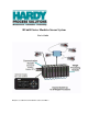
HI 6600 Series Modular Sensor System User Guide HI 6600 Series Modular Sensor System User’s Guide Hardy Process Solutions Document Number: 0596-0333-01 REV A Page | 1
HI 6600 Series Modular Sensor System User Guide Local Field Service Hardy has over 200 field technicians in the U.S., and more positioned throughout the world to assist you in your support needs. We also have factory engineers who will travel to your facility anywhere in the world to help you solve challenging applications.
HI 6600 Series Modular Sensor System User Guide Contents •••••• Contents .......................................................................................................................................... 3 Chapter 1......................................................................................................................................... 8 HI 6600 Series Overview ................................................................................................................
HI 6600 Series Modular Sensor System User Guide Using the HI 6110 Front Panel Display .................................................................................... 27 Mode Button ..................................................................................................................... 28 Channel Identification............................................................................................................... 29 System Discovery ..................................................
HI 6600 Series Modular Sensor System User Guide Count Operations ..................................................................................................................... 46 Determining Piece Count:................................................................................................. 46 Chapter 6....................................................................................................................................... 47 NetworkCommunications ..............................
HI 6600 Series Modular Sensor System User Guide Troubleshooting ............................................................................................................................ 84 Assembly Notes, Warnings & Cautions ....................................................................................... 84 Updating Instrument Firmware ........................................................................................... 85 Information Page ...................................................
HI 6600 Series Modular Sensor System User Guide Portion of the INPUT table used for Weigh Processing Modules (WPMs) ................. 115 Hardy Command Numbers ...................................................................................................... 116 Appendix B ................................................................................................................................. 118 Default Parameter IDs and Values ..................................................................
HI 6600 Series Modular Sensor System User Guide Chapter 1 HI 6600 Series Overview •••••• This Manual describes installation, setup and operating procedures for the HI 6600 Series Modular Sensor System. Be sure to read and understand all cautions, warnings, and safety procedures in this manual to ensure safe installation and operation of the instrument. Hardy Process Solutions sincerely appreciates your business. We encourage input about the performance and operation of our products from our customers.
HI 6600 Series Modular Sensor System User Guide The system is used for front end signal processing of strain-gage type sensors and load cells for all types of industrial and machine weighing applications. Operating blind or with an optional display, the Modular Sensor System conditions, converts and communicates stable processed weight readings from connected load sensors or scales to a variety of control and monitoring systems.
HI 6600 Series Modular Sensor System User Guide HI 6600 Series Model Numbers Page | 10 Model Number Description HI 6600-EIP Hardy Gateway Module - EtherNet/IP HI 6600-PB Hardy Gateway Module - Profibus-DP HI 6610-WP Weight Processing Module, no display HI 6110 Optional Multi-Channel Display
HI 6600 Series Modular Sensor System User Guide Chapter 2 Specifications and Features •••••• Chapter 2 provides specifications for HI 6600 series instruments. The specifications listed are designed to assist in the installation, operation and troubleshooting of your instrument. All service personnel should be familiar with this section before installing or repairing the instrument.
HI 6600 Series Modular Sensor System User Guide Note: Connecting 2 or more load cells requires a summing card or Junction Box. Non-linearity 0.0015% of full scale Common Mode Rejection 110 dB at or below 60 Hz Common Mode Voltage Range 2.5 VDC maximum (with respect to earth ground) Load Cell Excitation 5 VDC +/- 1.
HI 6600 Series Modular Sensor System User Guide Optional HI 6110 Front Panel Display Monochrome 480 x 272 LCD display with back light Five tactile keys for menu item selection Displays in either white on black or black on white IP66 rated when mounted on a smooth, rigid surface (minimum 16-gage) using the supplied gasket 2 watts maximum Environmental Requirements Operating Temperature Range -10ºC to 60º C (14º to 140º F) Temperature Coefficient Less than 0.
HI 6600 Series Modular Sensor System User Guide Each Hardy Process Solutions C2-certified load sensor outputs digital information used for calculating the calibration. When the HI 6600 series instrument reads the signals from the load sensors, it calibrates the scale based on the load sensor’s output plus a user-supplied reference point value (from 0 to any known weight on the scale).
HI 6600 Series Modular Sensor System User Guide Chapter 3 HI 6600 Hardware Installation •••••• Chapter 3 covers physical installation of HI 6600 Modular Sensor System. User and service personnel should read this chapter before installing or operating the HI 6600 Modular Sensor System. Safety Before you begin installing your HI 6600 series equipment, please review the important safety precautions below.
HI 6600 Series Modular Sensor System User Guide 2) Check to see that everything in the package matches the bill of lading. 3) If items are missing or you have any questions, contact Customer Service at: Hardy Process Solutions 9440 Carroll Park Drive San Diego, CA 92121 Phone: (800) 821-5831 International: (858) 292-2710 FAX: (858) 278-6700 Web Site: http//www.hardysolutions.com E-Mail: hardysupport@hardysolutions.com Record the model number and serial number of the HI 6600 series instrument.
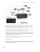
HI 6600 Series Modular Sensor System User Guide Overview of the HI 6600 Hardware Before installing the HI 6600 Series, familiarize yourself with the basic configuration as shown below. DC Power, Shield, Ports for HardyNet and a Termination switch can be found on the bottom of both the Hardy Gateway Module and the Weight Processing Modules. The RJ45 ports located on the bottom are used to connect the system using Cat5e cabling.
HI 6600 Series Modular Sensor System User Guide The MAXIMUM span between the first and last module that comprise a system is 500 feet (150 meters). Note: Use Heavy Gage DIN rail conforming to EN 60715 and EN 50022. Use of thin or light gage DIN rail is not recommended. Begin by installing the WPMs or HGMs onto the DIN rail as shown below.
HI 6600 Series Modular Sensor System User Guide Cabling the Units Together Once the units are all placed on a DIN rail, connect them together in a series using the RJ45 ports on the bottom of the units and Cat5e cable. The Cat5e cabling carries communications between the modules and distributes power from the Hardy Gateway Module to the Weigh Processing Modules.
HI 6600 Series Modular Sensor System User Guide WARNING - Be careful not to reverse the ground and hot wires, which can result in damage to the equipment. AVERTISSEMENT – Attention à ne pas inverser le sol et fils chauds, ce qui peut entraîner des dommages à l'équipement. A power-limited 12-24 VDC power supply (Class 2) must be used on the DC input wiring. DC power should be supplied by a clean primary line, directly from the DC power source.
HI 6600 Series Modular Sensor System User Guide Non-C2 load cell wiring Hardy load sensor with C2 Note: when connecting the HI 6600 series instrument to a junction box, the sense lines would be connected between the +Sen and –Sen connections for the junction box and the instrument. See the I/I Diagram for further detail. You can find the I/I Diagram in the Hardy website under Products> WARNING - Instrument power should be routed away from all other signal cables to avoid electrical interference.
HI 6600 Series Modular Sensor System User Guide The optional display for the HI 6600 series instrument can be mounted in a remote location up to 250 feet (75 meters) from the Hardy Gateway Module by modifying the supplied cable. Mounting the Optional Front Panel Display (1) Make sure that all Electrostatic Discharge (ESD) precautions are taken before and during installation. (2) A thin plastic template comes with the product.
HI 6600 Series Modular Sensor System User Guide i) Connect and hand-tighten the four screw rods into the Optional Front Panel display. ii) Place the gasket over the screw rods then slide the screw rods through the panel until flush with the surface. iii) Place washer and nut onto the screw rods sticking through the panel. Tighten nuts so that the gasket is fully compressed and that the metal bezel of the display is in contact with the panel.
HI 6600 Series Modular Sensor System User Guide Making Longer Display Interface Cables The terminal block uses a spring cage type contact. There is a slot provided to use an insert/release tool. The tool is a 2.0 mm x 0.4 mm wide flat blade screw driver. Inserting the end of the small screwdriver tool opens the cage contact and allows one wire to be inserted. Removing the insertion tool with bare conductor wire inserted will lock the connection.
HI 6600 Series Modular Sensor System User Guide Chapter 4 Instrument Configuration •••••• Menu Structure The menu tree below shows the location of commands and parameters used to configure and use the system.
HI 6600 Series Modular Sensor System User Guide The system can be set-up, calibrated and operated either through the built-in Webserver or through an optional front panel display. The menu structure above may be followed using either interface. Using the Webserver To use the Webserver, a connection must first be established between the Hardy Gateway Module and a connect PC.
HI 6600 Series Modular Sensor System User Guide Once connected, browse the webpages by following the menu tree presented in the beginning of this chapter. Changes are made by clicking the item and either selecting an option or inputting a value using your PCs keyboard. NOTE: Selections and inputs are ONLY saved to memory by clicking SAVE PARAMETERS in the webpage.
HI 6600 Series Modular Sensor System User Guide 2) Navigate UP and DOWN the submenus using the arrow keys, then select a menu by pressing the ENTER button. 3) Fixed options within a submenu are selected by using the UP & DOWN buttons to navigate to the choice, then by pressing ENTER key to select. Once an option is selected, back out of the submenu by pressing the LEFT arrow key.
HI 6600 Series Modular Sensor System User Guide The displayed mode on the instrument can also be changed by selecting DISPLAY MODE on the Operations webpage and choosing Gross, Net or Count from the drop-down menu or by sending the DISPLAY MODE command over communications.
HI 6600 Series Modular Sensor System User Guide Naming the Weight Processing Modules To ease identification of a particular Weight Processor Module, a meaningful name (ie: Ingredient C or BIN 8) may be assigned to the module by using Select Channel, Confirm Selection, then identifying the physical location of the module by pressing Identify On/Identify Off which will cause the LED on the selected module to blink.
HI 6600 Series Modular Sensor System User Guide Suggested Minimum Steps When Setting Up the Instrument For the First Time Choose a specific Weight Processor Module to set up by selecting a channel either from the front panel display or on the webserver.
HI 6600 Series Modular Sensor System User Guide Setup Parameter Menus The Setup Menus consists of the following parameters: Capacity Decimal Point Grads Instrument ID Motion Tolerance Operator ID Unit Capacity Parameter Scale Capacity is the scale's nominal operating capacity (the total weight capacity of the scale system). If this value is exceeded by six graduations, dashes appear on the front display. Communications to and from optional devices are not affected.
HI 6600 Series Modular Sensor System User Guide Instrument ID Use this parameter to assign a meaningful name to the system to make it easier to identify on a network. The assignment applies to the Gateway Module only, channels connected to the Gateway may also be assigned a name by following the Naming the Weight Processing Modules section located in the beginning of this chapter. Motion Tolerance Parameter The value you enter for Motion Tolerance sets the amount of deviation to allow for your process.
HI 6600 Series Modular Sensor System User Guide Filter Parameter Menu There are two parameters in the Filter menu NumAverages (Number of Averages) WAVERSAVER NumAverages Parameter The value you enter for NumAverages (the Number of Averages) sets the number of weight readings used to compute a sliding average of displayed weight. This helps reduce the effects of material impact and/or vibration if material does not enter or exit the scale evenly.
HI 6600 Series Modular Sensor System User Guide Calibration The parameters in the System Calibration menu are shown below. C2 or eCAL Sensitivity Gravity Ref Wt (Reference Weight) Do C2 Calibration Cal Tol (Calibration Tolerance) Num Dev (# of C2 Sensors) Hard Cal Cal Tol (Calibration Tolerance) Sensitivity Cal Lo Wt (Zero Reference Point) Do Cal Lo Span Wt (Span Weight) Do Cal Hi This section describes C2 or eCAL and traditional calibration procedures.
HI 6600 Series Modular Sensor System User Guide WARNING - Binding on a scale/vessel or load cell does not allow the load cell free vertical movement and may prevent the instrument from returning to the original zero reference point. AVERTISSEMENT – Lier sur une échelle / récipient ou cellule de charge ne permet pas la cellule de charge libre circulation verticale et peut empêcher l'appareil de revenir au point de référence zéro d'origine.
HI 6600 Series Modular Sensor System User Guide NOTE: The operating range for the scale in this example is 5-10 mVDC with a 500 pound weight range. After zeroing the instrument, the 0 reading refers to the zero reference point and not absolute 0 mVDC or absolute 0 weight. NOTE: Load cell/point measurements are checked with a digital voltmeter at the load cell connector on the front of the module or by using INTEGRATED TECHNICIAN with a Hardy IT Junction Box.
HI 6600 Series Modular Sensor System User Guide Cal Tolerance Parameter Sometimes, the contents of the vessel you are weighing are in motion. Cal Tolerance allows you to set a value that determines the amount of motion that the system can tolerate and still calibrate. In other words, the value you enter for Calibration Tolerance sets the amount of deviation to allow during the calibration process. This value must be greater than or equal to the base motion value and/or the Graduation Sizes.
HI 6600 Series Modular Sensor System User Guide Page | 39
HI 6600 Series Modular Sensor System User Guide C2 and eCAL Calibration Process Navigate to the C2and eCAL menu from the Web brower or on the front panel display 1) Check to make sure the number of load cells displayed in the Num Devices menu corresponds to the actual number of C2 devices installed. If the number varies, check to ensure that each load cell/point cable connection is securely fastened and that each load cell/point cable is not broken.
HI 6600 Series Modular Sensor System User Guide Hard Calibration Hard Calibration is the method of calibration that uses test weights. We recommend that the span total 80 to 100% of the scale live load capacity and the weights be distributed uniformly on/in the scale. Put a load (weight) on the scale or vessel. For a full load test you can put 80% to 100% of the expected weight you will see in your process on the scale or vessel.
HI 6600 Series Modular Sensor System User Guide setting/verifying the Span Weight value executing this command will run the Hard Calibration process using the Cal Tolerance, Span Weight, and Sensitivity parameter settings. Span Weight Parameter The Span Weight value is the weight of the object that is being placed on the scale to set the “High” calibration point with respect to the “Low” calibration point set using the Cal Lo Weight parameter.
HI 6600 Series Modular Sensor System User Guide Chapter 5 Instrument Operation •••••• Operations The following parameters are used for instrument operations: Tare Operations o Tare Amount o Tare Offset o Tare Zero Operations o Zero Tolerance o Zero Amount o Zero Auto Mode o Auto Mode Enabled o Auto Mode Disabled Count Operations o Count Enable o Unit Weight o Sample Size o Weigh Sample Tare Parameters and Commands Tare Amount The Tare Amount parameter displays the total
HI 6600 Series Modular Sensor System User Guide Tare Offset The value you enter for Tare Offset allows the user to avoid pushing the Tare button each time he/she places an empty container on the scale. RANGE: .000001 - 999999. (default 0.0) From the Web page: enter the Tare Offset in the text box provided. Using the Front Panel Display: enter the Tare Offset using the arrow keys.
HI 6600 Series Modular Sensor System User Guide Zero Amount The Zero Amount parameter is READ ONLY and displays the amount that has been "zeroed" from the scale. On the Web page or Using the Optional Front Panel Display: Enter the Zero Amount on the Operations Menu web page or enter the Zero Amount using the arrow keys on the operations menu on the front panel. Zero Command On the Web page: click the Zero button to zero the scale.
HI 6600 Series Modular Sensor System User Guide Count Operations The count mode allows the unit to be calibrated and used as a piece counter. This mode allows the user to "count" the number of pieces placed on the scale.
HI 6600 Series Modular Sensor System User Guide Chapter 6 Network Communications •••••• Chapter Six contains step-by-step instructions for configuring the HI 6600 Hardy Gateway Module for communications with external networks, often interfacing with a PLC, DCS or PC network. We recommend reading these procedures because having a correct configuration is necessary to ensure trouble-free operation.
HI 6600 Series Modular Sensor System User Guide Maximum Number of Channels Supported for PLC Communication Formats EtherNet/IP: 30 channels (496 bytes) Modbus-TCP: 14 Channels (240 bytes) Modbus-RTU: 14 Channels (240 bytes) Profibus-DP: 10 Channels (176 bytes) Ethernet TCP/IP Network Configuration NOTE Do not confuse the on-board Ethernet TCP/IP communication with EtherNet/IP®.. EtherNet/IP is an industrial protocol that does not transmit Web traffic.
HI 6600 Series Modular Sensor System User Guide IP address. If you are required to use a Fixed IP addresses, refer to the section Fixed IP Configuration Using the Optional Front Panel below. For automatic IP assignment (DHCP), use the following steps: Enable DHCP The Enable DHCP parameter enables the network to automatically assign an IP address when DHCP is enabled in the HI 6600 HGM. When DHCP is disabled or the network is unable to assign an IP address the Fixed IP address is used.
HI 6600 Series Modular Sensor System User Guide DNS Server Parameter The DNS Server parameter provides the host name when the HI 6600 series instrument is communicating with a remote host. On the Web page or through the Optional Front Panel: enter the DNS Server Parameter in the text box provided. Fixed IP Configuration The HI 6600 series instrument can be configured to use any Fixed IP address.
HI 6600 Series Modular Sensor System User Guide Windows PC Configuration: Windows 2000 1) After starting your computer, click the Start button. 2) Click on Settings > Control Panel to display the Windows Panel. Control 3) Click the Network icon to display the Network dialog. 4) Click on TCP/IP; then click the Properties button to open TCP/IP Properties dialog. the 5) Click the IP Address tab.
HI 6600 Series Modular Sensor System User Guide 5) Click on Change Adapter Settings in the left-hand column. 6) Right click on Local Area Connection and select Properties. 7) Click on Internet Protocol Version 4 (TCP/IPV4) 8) Click the Properties button to open the Internet Properties (TCP/IP) Properties dialog. 9) If the ‘Use the Following IP Address’ box is already checked, then write down the displayed IP Address and jump to the Direct Connect Configuration – HI 6600 section below.
HI 6600 Series Modular Sensor System User Guide Once you have the Ethernet TCP/IP setup, there is no other configuration needed through either the web page or the Optional Front Panel for the Ethernet/IP setup in the HI 6600. Refer to the I/O tables in Appendix A for an understanding of the data and format for the EtherNet/IP communications.
HI 6600 Series Modular Sensor System User Guide The EIP diagnostic parameters count the number of packets of various types received (in) or transmitted (out). TCP in 24 TCP out 22 UDP out 9 UDP in 9 UDP IO in 0 UDP IO out 0 PCCC in 0 PCCC out 0 TCP is used for most explicit or unconnected messages. The usual sort of EtherNet/IP connection is one in which packets are sent and received at some specified RPI (requested packet interval).
HI 6600 Series Modular Sensor System User Guide Ethernet UDP Parameters Ethernet UDP enables the HI 6600 series instrument to send messages, datagrams, to other hosts on the IP network. Hardy Port The Hardy Port provides the service port which is combined with the IP address to provide a unique application socket. The Hardy Port value can be any 16-bit value between 0 and 65,535.
HI 6600 Series Modular Sensor System User Guide The Modbus TCP and Modbus RTU Diagnostics screen may help with troubleshooting connection problems with the HI 6600 series units. The Modbus Diagnostics parameters count the number of frames received by the Hardy HI 6600 series and how many of these are valid compared to error frames. In this case, the instrument is correctly reporting that it is not connected and is not receiving any frames.
HI 6600 Series Modular Sensor System User Guide The Modbus Diagnostics parameters count the number of frames received by the Hardy HI 6600 series and how many of these are valid compared to error frames. In this case, the unit is correctly reporting that it is not connected and is not receiving any frames. Installing the Hardy Modbus-Link Test Package If you do not have a PLC or other client, Hardy has provided the Hardy Modbus-Link Client to test communications with the HI 6600 unit.
HI 6600 Series Modular Sensor System User Guide 2) Click Connect n the Connection pull-down menu, to display the TCP/IP Connection form. 3) If TCP/IP is not selected, select it from the pull-down list. 4) Type the address of the HI 6600 module you want to communicate with into the IP Address text box and click OK.
HI 6600 Series Modular Sensor System User Guide The red “No Connection” disappears and the values at the top of the page start to change. You are now connected from your PC to the HI 6600 weight processor. 5) On the Setup pull down menu select Poll Definition and select the function 04 INPUT REGISTER and the Adress 0 and Length as 8 +(8 * x) where x = the number of Weight Processing Modules to a maximum of 120. 6) On the Hardy Modbus-Link page. Display pull-down menu, select Float Inverse.
HI 6600 Series Modular Sensor System User Guide 7) From the DISPLAY drop down, select the Long Inverse selection. This will allow us to write an integer value into the non-float registers. 8) From the FUNCTION drop down list select Read/Write registers, or click button 23 to open the Write multiple registers display. 9) Double click on the first register and the Enter Value box appears. Enter the new value you wish to write to this register.
HI 6600 Series Modular Sensor System User Guide 10) Click on OK to accept the value and click on the Send button to send it to the HI 6600. Click OK to the Response OK message.
HI 6600 Series Modular Sensor System User Guide Modbus-RTU (over RS-485) Modbus-RTU Commands and Parameters Slave Address Parameter The Slave Address parameter is a unique network address between 1 and 247 assigned to the HI 6600 series instrument. On the Web page: select the communication menu and then select the Modbus RTU submenu, and left click inside the Slave Address text field and enter the Slave Address assigned to the HI 6600 series instrument.
HI 6600 Series Modular Sensor System User Guide On the HI 6110 optional display: select the communication menu and use the UP or DOWN button to select the Modbus-RTU submenu, then select the Baud Rate menu item. The current Baud Rate value will be displayed, press the ENTER or the RIGHT button if the value needs to be modified. Parity Parameter The Parity parameter has three options, EVEN, ODD, or OFF.
HI 6600 Series Modular Sensor System User Guide Modbus Setup • Slave Address may be set to any number in the range of 1-247. • Set Baud Rate parameter to match the settings of the Modbus master • Set Parity to match the settings of the Modb Modbus Functions The Modbus functions allowed in the HI 6600 are: • • • • Function 3: Modbus Read Holding Registers Function 4: Modbus Read Input Registers Function 6: Modbus Write Single Register Function 16 (0x10): Modbus Write Multiple Registers.
HI 6600 Series Modular Sensor System User Guide • 6: WEIGHT SAMPLE CMD: Write a #6 to the command register to run the Weigh Sample command to set up the calibration of the Counts (if enabled). o o Status Error code 1 (motion) Status error code 2 (A/D error) • 0x64 (100 decimal): CAL LOW CMD. Write a 0x64 hex to the command register to perform the low step of a traditional calibration.
HI 6600 Series Modular Sensor System User Guide Wiring For Profibus, connect the two wires to pins 3 and 4. GND SHIELD Signal DO Not Ground Connect TX+ TXD+ /RXD+ TXTXD-/RxD- Non-inverting Inverting Profibus Configuration Profibus-DP operates using a cyclic transfer of data between master(s) and slave(s) on an RS-485 network. An assigned master periodically requests (polls) each node (slave) on the network. The HI 6600 is a slave device.
HI 6600 Series Modular Sensor System User Guide NOTE Profibus Node Address #5 is the lowest number that can be used by a slave device. 2) Select termination drop down and select termination condition. Termination maybe be set to Enable, Disable or Link. Link means that the termination is set on or off depending on whether pin 2 of the connector is low (on) or high (off). There is an internal pull up on pin 2 that will set the termination off if nothing is connected to it.
HI 6600 Series Modular Sensor System User Guide Profibus-DP .GSD File All devices connected to a Profibus-DP network require a *.gsd file. The *.gsd file contains all the parameters including the baud rate, table formats and necessary data required by the network PLC when an HI 6600 or HI 6510 is connected to the network. You must download the proper *.GSD file from the Hardy website. 1) Navigate from the products section to the HI 6600 web page.
HI 6600 Series Modular Sensor System User Guide Configuring Profibus from the Front Panel 1) 2) 3) 4) 5) 6) 7) 8) 9) 10) Press the Configuration key Down arrow to Communications; press enter. Select Profibus-DP; press enter. Select Termination; press enter Up or down arrow to make termination selection. Press enter to select. Down arrow to select Serial Option; Press enter to toggle between Profibus-DP and Modbus. Select Profibus-DP and press enter. Down arrow to Node.
HI 6600 Series Modular Sensor System User Guide 6) Click OK to set the Node Address. 7) The HI 6600 Series module appears in the Profibus Network. 8) Click in the module properties at slot 1. In the catalog, expand the module properties and make selection for "48 bytes in and out".
HI 6600 Series Modular Sensor System User Guide 9) Once the selection has been made, you should see the input and output words showing the associated addresses in the table as shown. NOTE Page | 71 The HI 6600 or HI 6510 Series Input and Output Sizes are expressed in 32 bit words. 12 words input and 12 words output.
HI 6600 Series Modular Sensor System User Guide 9) Click the Download Icon to download the configuration to the PLC and open the Select Destination Module dialog box. 10) Click OK to open the Select Station Address Dialog box; then click OK again. A status box will show the progress of configuration download to the PLC. 11) When the download is complete the HW Config dialog box should look something like this.
HI 6600 Series Modular Sensor System User Guide USB Memory Stick The HI 6600 series provides an interface to an external USB memory stick that allows HI 6600 parameters to be saved, restored or copied to another instrument. The USB memory stick commands can be activated through the web interface or the display panel. From the front keypad: To access the USB Menu, select Configuration > Enter, Communications > Enter, USB >Enter, UP or DOWN arrow to Save or Restore > Enter.
HI 6600 Series Modular Sensor System User Guide Chapter 7 Security •••••• Chapter 7 covers the security menu, which allows the user to lock out different levels of the menu hierarchy. The user configurable security settings only limit access through the Optional Front Panel to ensure the consistency of the instrument setup and weighing process. Parameter configuration through the network is unaffected by these security settings.
HI 6600 Series Modular Sensor System User Guide The changes to the calibration and read only security features are updated when you exit the security submenu and return to the configuration menu; while changes to the display, keypad, or configuration security settings are updated when the operator exits the configuration menu. The factory default for the security menu is to disable all lock modes and to preset each of the security passwords to 1234.
HI 6600 Series Modular Sensor System User Guide The display lock flowchart below shows the options and features when the display lock is enabled.
HI 6600 Series Modular Sensor System User Guide The following list explains the operation and features available if the correct 4 alphanumeric character password is entered by the operator. 1) Display Password: The current display lock setting is saved. The display lock is set to disabled and the MODE button is unlocked, enabling the operator to view the current Gross or Net weight on the Optional Front Panel display.
HI 6600 Series Modular Sensor System User Guide The Keypad Lock While the keypad lock is enabled the Mode, Zero, Tare, and Configuration buttons are disabled regardless of the configuration lock setting. If the ENTER button is pressed the “Enter Password” page will appear on the display. At this level of security the operator can enter one of two possible passwords for the keypad lock or the configuration lock. The keypad lock flowchart below shows the options and features when the keypad lock is enabled.
HI 6600 Series Modular Sensor System User Guide The following list explains the operation and features available if the correct 4 alphanumeric character password is entered by the operator. 1) Keypad Password: The current keypad lock setting is saved. The MODE, TARE, and ZERO buttons are unlocked, enabling the operator to tare or zero the scale. Pressing the ENTER button a second time returns the keypad lock to its original setting.
HI 6600 Series Modular Sensor System User Guide Figure 3: Configuration Lock Flowchart The following list explains the operation and features available if the correct 4 alphanumeric character password is entered by the operator. Configuration Password: The current configuration lock setting is saved. The CONFIG button is also enabled allowing the operator to open the configuration menus.
HI 6600 Series Modular Sensor System User Guide The Read Only, Security & Calibration Locks There are three additional levels of security once the operator is within the configuration menu. These limit access to sensitive parameter settings such as calibration, security settings, and network settings. If the operator has been given permission to access the configuration menu, the operator will at a minimum be able to view all the parameters except the security parameters.
HI 6600 Series Modular Sensor System User Guide Modifying the Security Parameters To view or modify the security parameters use the UP or DOWN button to select the security menu then press ENTER. Figure 5: Parameters Lock Flow Chart To modify the security feature use the UP or DOWN button to select the security feature then press the ENTER button.
HI 6600 Series Modular Sensor System User Guide Modifying the Calibration Parameters The calibration security locks out users from seeing any calibration parameters until you enter the correct calibration password. To modify the calibration parameters use the UP or DOWN button to select the calibration menu and press the ENTER button.
HI 6600 Series Modular Sensor System User Guide Chapter 8 Troubleshooting •••••• Chapter 8 provides procedures for troubleshooting the electrical, mechanical and firmware elements of the HI 6600 series instrument and for using Hardy’s Integrated Technician (IT®) software utility to isolate problems. Flow charts provide troubleshooting procedures for the Gateway Module, the WPM modules, load cells, and cabling. NOTE Never run Hardy’s Integrated Technician testing while in a production mode.
HI 6600 Series Modular Sensor System User Guide This chapter describes several tests that can shorten the time for troubleshooting. Most problems require the use of two or more tests to determine the cause. If a problem is isolated to a load cell, it may not mean the load cell is the damaged component. Mechanical imbalances and system piping stress (lack of piping flexures, pressure hoses draped over, pipes etc.) can make a load cell or Weight Processor Module seem to be the problem.
HI 6600 Series Modular Sensor System User Guide To change to a different WPM Channel, just select it from the pull down menu. To update firmware on a WPM version, first select it and change the channel, then select Begin Programming.
HI 6600 Series Modular Sensor System User Guide Common Error Messages A/D Convert Error! - Load Cells input out of range. Motion Error! - Check Motion Tolerance Settings and Retry Too Lo Error! - Verify that the load cell signal level is 0-25 mV. Verify that there is enough weight on the scale. Too Hi Error! - Verify that the load cell signal level is 0-25mV. Verify that there is too much weight on the scale.
HI 6600 Series Modular Sensor System User Guide channels to each HI 6610 Weight Processing Module. The test for pass or fail may take 30 seconds to settle. It will always show the load cells as fail when the test is started. The reduced voltage is a Yes or No selection. Then run the J-box test 1 as appropriate. A more detailed explanation of each section of the test follows below: Stability Test ALL Stability: Gross = 0.9lb RAW 32918 Mean 0.17 Variation Results OK 0.
HI 6600 Series Modular Sensor System User Guide Further investigation to isolate system problems requires the use of hand tools and multi-meters or the INTEGRATEDTECHNICIAN Junction or Summing Box and using the IT© Test section. NOTE INTEGRATED TECHNICIAN ® (IT) is a registered trademark of Hardy Process Solutions. Weight This displays the amount of force seen by all load cells installed in the summing junction box.
HI 6600 Series Modular Sensor System User Guide and press Do IT Test. The Dwell test for pass or fail takes 30 seconds to settle. Until it settles, it will always show “fail” when the test is started. If the browser times out during the test, refresh your browser until the results appear. NOTE Page | 90 Warning: Do not install your Junction Box or summing card in areas susceptible to high vibrations. The relays on the circuit board can chatter and affect your weight readings.
HI 6600 Series Modular Sensor System User Guide General Troubleshooting Flow Chart Index Page | 91
HI 6600 Series Modular Sensor System User Guide A - Electrical and Mechanical Review Page | 92
HI 6600 Series Modular Sensor System User Guide A1.
HI 6600 Series Modular Sensor System User Guide B.
HI 6600 Series Modular Sensor System User Guide B1 - Guidelines to Verify Electrical Installation Page | 95
HI 6600 Series Modular Sensor System User Guide B2 - Guidelines to Verify Mechanical Installation Page | 96
HI 6600 Series Modular Sensor System User Guide B3 - Verify Configuration/Filter Settings to Improve Stability Page | 97
HI 6600 Series Modular Sensor System User Guide C - Integrated Technician and Stability Test Overview Page | 98
HI 6600 Series Modular Sensor System User Guide E Non-Return to Zero (System with IT Summing Card.
HI 6600 Series Modular Sensor System User Guide F. Verify Individual Load Sensor Millivolt Output readings Testing an individual load sensor output requires an IT summing card or Millivolt meter with two decimal place resolution.To determine the sensitivity and parameters for your load sensor, use the load sensor certificate or read the C2 chip with the utility found under the Diagnostic menu. Example: A 3mV/V Load sensor produces approximately 3.0000 mV/V at rated load.
HI 6600 Series Modular Sensor System User Guide G- Calibration Errors During Calibration Page | 101
HI 6600 Series Modular Sensor System User Guide H.
HI 6600 Series Modular Sensor System User Guide J- Electrical Inspection Page | 103
HI 6600 Series Modular Sensor System User Guide K - Installation Check Points Page | 104
HI 6600 Series Modular Sensor System User Guide M.
HI 6600 Series Modular Sensor System User Guide Tests and Diagnostics The Test and Diagnostics menus provide an expanded view of how the weight processor and scale are working. You can run several tests from either the test links on the Web Diagnostic page or the Optional Front Panel Test menu. Each test is described in its own subsection below. You can also obtain information that a Hardy representative may ask for if you make a request to Technical Support.
HI 6600 Series Modular Sensor System User Guide Parameters Parameters are the first listed hyper- link at the base of the Diagnostics page. Click that link to display the Parameters page. Note the scroll bar on the right of the list. The steps below explain how you can duplicate the configuration of one HI 6610 or HI 6600 to use in configuring another HI 6610 or HI 6600 for sending a copy of your parameters to hardysupport@hardysolutions.com To copy the parameters: 1) Right click in the parameter list.
HI 6600 Series Modular Sensor System User Guide System and Load Cell Tests Overview of Typical Load Cell System The typical system consists of one or more load cells/points, a summing junction box, and an HI 6600 Weight Processor. Load sensor - Used to measure pressure, weight, or torque, the sensor is a strain gauge- based force transducer that generates an electrical signal proportional to the load applied. This can be done using either tension or compression type load sensors.
HI 6600 Series Modular Sensor System User Guide INTEGRATED TECHNICIAN INTEGRATED TECHNICIAN® (IT) is an optional diagnostics utility that enables the operator to rapidly troubleshoot individual load cells. The option requires an HI 215IT or HI 6010IT Summing Box (shown above) that provides distinct inputs for each load cell. Without the HI 215IT or HI 6010 Summing Box, it is difficult to isolate the signals from different load cells.
HI 6600 Series Modular Sensor System User Guide WARNING - DO NOT PERFORM THE STABILITY TEST DURING PRODUCTION. THE TEST ACTIVITIES CAN CAUSE INCORRECT READINGS. AVERTISSEMENT – Ne pas effectuer le test de stabilité lors de la production. Ces tests peuvent résulter à des lectures incorrectes. Running the Stability Test from the Web Interface A Stability Test column on the IT test results display (see picture above) shows PASS or FAIL for each load sensor.
HI 6600 Series Modular Sensor System User Guide Weight and Voltage Tests The Weight and Voltage tests are used to diagnose a weighing system and, if certain types of problems are indicated, determine their source. It provides the total scale input to the instrument such as mV, mV/V and Weight in the units selected (i.e. lbs, kg, oz, g). Weight and Voltage Test from the Web interface Since the IT Web page shows all the weight and voltage values at once, it is the preferred method for troubleshooting.
HI 6600 Series Modular Sensor System User Guide The screen shows the individual load sensors in dwell mode. Using the right+ left button, move from Sensor to Sensor. The pass/fail test requires 15-30 seconds to complete testing. IT Dwell – Jbox1 RAW Variation mV/V Weight RTZ Page | 112 Channel x (x/5) Waversaver Results OK 0.45 0.00 0.0219 -0.
HI 6600 Series Modular Sensor System User Guide Appendix A Communications I/O Table •••••• I/O Tables for Communications to PLCs The following I/O table description is common for the following communication protocol in the HI 6600 series: EtherNet/IP Profibus-DP Modbus-TCP Modbus-RTU (over 485) For a full list of command parameters, please see Appendix B, Default Parameter IDs and Values under Communications Parameters.
HI 6600 Series Modular Sensor System User Guide OUTPUT Table Description Portion of the OUTPUT table used for the Hardy Gateway Module (HGM) The first four variables in the output table, Command, Aux Command Information, Parameter ID, and Parameter Value, are used to send commands either the Hardy Gateway Module (HGM) or to a specific Weight Processing Module, to write new parameter values, read existing parameter values, or read data values such as COUNT, or ROC, etc.
HI 6600 Series Modular Sensor System User Guide The 16-bit value, Gateway Status, provides two pieces of information, the bottom 14-bits provide the current state of all the major functions within the Hardy Gateway Module (HGM) and the top 2 bits of the 16-bit value, are a cyclic “IO table count”, which will increment by a count of one every time a new “input table” is generated, following a 0, 1, 2, 3 then repeat cycle.
HI 6600 Series Modular Sensor System User Guide Hardy Command Numbers Here is a list of Hardy command numbers: Command 0 1 2 4 5 6 0x64 (100 0x65 (101 0x66 (102 0x1000 (4096 0x1001 (4097 Page | 116 Command Read Parameter Zero Cmd Tare Cmd Write Non-Volatile Cmd (Reserved) Weigh Sample Cmd Cal Low Cmd Cal High Cmd C2 Cal Cmd Write Integer Cmd Write Float Cmd 0: READ PARAM CMD.
HI 6600 Series Modular Sensor System User Guide • 0x64 (100 decimal): CAL LOW CMD. Write a 0x64 hex to the command register to perform the low step of a traditional calibration. The status register will read 0 if this command succeeds: o Calibration_Fail 1 o Calibration_Fail_Motion 3 o Calibration_Fail_Adc_Error 4 • 0x65 (101decimal): CAL HIGH CMD. Write a 0x65 hex to the command register to perform the high step of a traditional calibration.
HI 6600 Series Modular Sensor System User Guide Appendix B Default Parameter IDs and Values •••••• Default Parameters and Values Table Below is a list of parameters, their ID numbers and their defaults for reference.
HI 6600 Series Modular Sensor System User Guide Menu SubMenu Parameter Name Language (menu items) Language Menu SubMenu Parameter Name Operations Operations Operations Operations Operations Operations Operations Operations (menu items) (menu items) PieceCount PieceCount PieceCount PieceCount TareOperations TareOperations Gross Weight Net Weight Unit Count Unit Weight Sample Size Count Enable Tare Offset Tare Amount Menu SubMenu Parameter Name Security Display Security Security Security Sec
HI 6600 Series Modular Sensor System User Guide Appendix C Drawings & Templates •••••• II Diagrams NOTE Full size II Diagrams are available on the Hardy Process Solutions website under products, Weight Processors, HI 6600. Select the Docs & Programs tab to locate and download the drawings you desire. The following pages show II diagrams for the Hardy Gateway Module and the Weight Processing module.
HI 6600 Series Modular Sensor System User Guide Image of HI 6600 Hardy Gateway Module II Diagram Page | 121
HI 6600 Series Modular Sensor System User Guide Image of HI 6610 Weight Processing Module II Diagram Page | 122
HI 6600 Series Modular Sensor System User Guide Optional HI 6110 Display Panel Mounting Template Page | 123
HI 6600 Series Modular Sensor System User Guide Appendix D Spare Parts •••••• Spare Parts Table Part Reference Description Quantity HI 6610 Weight Processing Module 2140-0092-0 J1, 3-pin Power Connector 1 2140-0139-09-0 2, 9-pin Load Cell Connector 1 6032-0082-0 Cable Assy, Ethernet Patch, Cat 5E, Black (one per weight module) 1 2140-0092-0 J1, 3-pin Power Connector 1 2140-0139-9 J3, 9 pin Serial Connector 1 6032-0082-0 Cable Assy, Ethernet Patch, Cat 5E, Black (one per weight module)
HI 6600 Series Modular Sensor System User Guide Appendix E Wiring Junction Boxes or Summing Cards •••••• Connecting to Hardy Junction Boxes or Summing Cards To connect more than one load cell to a Hardy HI 6610 WPM module, you will need a summing card or junction box to aggregate the signals to provide a singular weight reading. While a platform, bench or floor scale has a built in summing card to perform this function, load cells need an external Summing Card or Junction Box.
HI 6600 Series Modular Sensor System User Guide NOTE When connecting two IT Junction Boxes together to connect 8 load points, you must run an external 5 Volt DC power supply if you will run C2 cabling a long distance. You cannot use a higher voltage power supply due to over voltage damage to your Hardy controller. For more information, visit the Hardy Knowledgebase and search under external excitation voltage. Excitation monitor is the current draw on the excitation voltage from the weight controller.
HI 6600 Series Modular Sensor System User Guide At Hardy, we believe that industrial weighing solutions should be EASY to engineer and operate. We believe that simplicity delivers the LOWEST TOTAL COST to own. That’s why our solutions are EASIER to install, integrate, commission, diagnose and maintain. Want MORE PRODUCTIVITY at the LEAST TOTAL COST to own? Call Hardy to discover how Today! 9440 Carroll Park Drive, San Diego, CA 92121 Telephone: 1-800-821-5831 FAX: (858) 278-6700 Web Address: http://www.