HI HLPS SERIES LOAD POINT ASSEMBLIES OPERATION AND INSTALLATION MANUAL Corporate Headquarters 9440 Carroll Park Drive, Suite 150 San Diego, CA 92121 Phone: (858) 278-2900 FAX: (858) 278-6700 Web-Site: http://www.hardysolutions.com Hardy Process Solutions Document Number: 0596-0237-01 Rev G Copyright 1999-2013 Hardy Process Solutions All Rights Reserved. Printed in the U.S.A.
Local Field Service Hardy has over 200 field technicians in the U.S., and more positioned throughout the world to assist you in your support needs. We also have factory engineers who will travel to your facility anywhere in the world to help you solve challenging applications.
CAUTION: UNPACK WITH CARE WHEN UNPACKING, DO NOT DISCARD THE PACKING CASE OR ANY PACKING MATERIAL, UNTIL THE CONTENTS OF THE PACKING CASE ARE INSPECTED AND CAREFULLY COMPARED WITH THE SHIPPING DOCUMENTS.
Table of Contents Table of Contents General Information - - - - - - - - - - - - - - - - - - - - - - Three Load Point Types - - - - - - - - - - - - - - - - - - - - Unpacking - - - - - - - - - - - - - - - - - - - - - - - - - - - Installation of the Ground Strap - - - - - - - - - - - - - - - - - Site Preparation - - - - - - - - - - - - - - - - - - - - - - - - Precautions - - - - - - - - - - - - - - - - - - - - - - - - - - Basic Engineering Principles for Positioning Load Point Assemblies Principle #1 - - - -
HI HLPS SERIES LOAD POINT ASSEMBLY ii
OPERATION AND INSTALLATION MANUAL Congratulations, on your purchase of the Hardy Process Solutions Load Point Assembly. This product, is engineered to set a new standard in load point assemblies. Hardy combined new innovations with previously extra cost features and just plain common sense features and provided you with optimum performance unequaled anywhere. General Information The Hardy HI HLPS Hermetic Load Point System provides accurate output in the most demanding applications.
HI HLPS SERIES LOAD POINT ASSEMBLY Three Load Point Types FIG. 1: FIXED PIN LOAD POINT FIG. 2: BUMPER PIN LOAD POINT FIG.
OPERATION AND INSTALLATION MANUAL Unpacking Installation of the Ground Strap • Do not remove the load point assembly from it’s packaging until just before installation. Although the load sensor is designed for harsh environments, it is a precision instrument and should be treated as such. • Inspect the box, packing and the load point assembly for any signs of damage that might occur during shipment. Since almost all of the load point assemblies are shipped F.O.B.
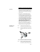
HI HLPS SERIES LOAD POINT ASSEMBLY if you are shipping the vessel fully assembled on the load points. Step 4. Save the two shortest machine screws (the hex bolts that fasten the shipping brackets to the base plate). You will use them to install the ground strap. (See Fig. 1-4) Step 5. Place one of the ground strap connectors over the threaded hole in the base plate. These are the ones that fastened the shipping bracket to the base. (See Fig. 5) FIG. 5: GROUND STRAP INSTALLED NOTE: Page 4 Step 6.
OPERATION AND INSTALLATION MANUAL Site Preparation Precautions • All mounting surfaces for the base and loading plate must be level. The distance between the mounting surface of the loading plate and base must be within 1/32” of the nominal height, “H”. The Load Point Assemblies in a system must be level to within +/- 0.5o. • When mounting the base plate on concrete, use grout to level the plate. • Do any welding before installing the load points.
HI HLPS SERIES LOAD POINT ASSEMBLY Principle #2 • All scales should include one fixed pin-load mount (F), one bumper pin-load mount (B). All other load point assemblies in a scale must be the free-sliding mount (S). Principle #3 • Place the fixed pin-load mount and the bumper pin load mount as far as possible from each other. • The fixed pin load mount and the bumper pin load mount must be mounted in the same longitudinal axis.
OPERATION AND INSTALLATION MANUAL Round Vessel with 3 Load Point Assemblies FIG. 6: THREE LOAD CELLS IN ROUND CONFIGURATION Round Vessel with 3 Load Point Assemblies - Angle Config. #1 S F <45 o B FIG.
HI HLPS SERIES LOAD POINT ASSEMBLY Round Vessel with 3 Load Point Assemblies - Angle Config. #2 FIG. 8: ANGLE FOR ALL LOAD CELLS IN ROUND CONFIGURATION NOTE: Load Cells can be oriented with cables pointed either in or out. For three load point systems, the mounting locations should be spaced120 degrees apart. For four load point systems the mounting locations should be spaced 90 degrees apart. Square Hopper with 3 Load Point Assemblies - Even Load Distribution S F O B FIG.
OPERATION AND INSTALLATION MANUAL Square Hopper with 3 Load Point Assemblies - Uneven Load Distribution B S F FIG. 10: ANGLE FOR THREE LOAD CELLS IN SQUARE CONFIGURATION NOTE: This configuration is an exception to the even load distribution principle. Use this configuration in circumstances where you arrange several hopperin close proximity to each other. Round Vessel with 4 Load Point Assemblies FIG.
HI HLPS SERIES LOAD POINT ASSEMBLY FIG. 12: FOUR LOAD CELLS FACING INWARD IN ROUND CONFIGURATION Typical 4 - Load Point Assembly Installation FIG.
OPERATION AND INSTALLATION MANUAL Typical 6 - Load Point Assembly Installation FIG. 14: SIX LOAD CELLS POSITIONED IN A RECTANGULAR CONFIGURATION NOTE: In case there is doubt concerning load point assembly installation, contact your local Hardy Process Solutions dealer, Application Engineering Department, or Customer Support Department for assistance. You can orient the load point assemblies to meet your system installation requirements. All load point assemblies can be rotated 360o in 90o increments.
HI HLPS SERIES LOAD POINT ASSEMBLY For scales that must meet NIST Class 3 (OIML Class 3) specifications: 1. Maximum base plate angle variation: 0.2 degrees. 2. Maximum top plate angle variation 0.5 degrees. For scales that must meet accuracy specifications => 0.1% 1. Maximum base plate angle variation 0.2 degrees 2. Maximum top plate angle variation 1 degree. Installation Procedures Pre-Installation Procedures Step 1.
OPERATION AND INSTALLATION MANUAL Installing Load Point Assemblies with Anchor Bolts Installing the Base Plate The outline drawing located on the www.hardysolutions.com Web Site provide the Base Plate and Top Plate dimensions for the Load Point Assembly. They include the thru hole diameters and center distances. Step 1. Make sure that the concrete foundation is level. Step 2.
HI HLPS SERIES LOAD POINT ASSEMBLY FIG.
OPERATION AND INSTALLATION MANUAL FIG. 17: ANCHOR BOLTS TEMPLATE Step 3. Use wood or metal to create the templates. The size of the template depends on the size of the anchor bolts. Step 4. Mark a point on on each template. Then, using the I/I diagram, make another mark on the template measuring from the thru hole center points on the base plate. Step 5. Drill the thru holes the same size as the base plate thru holes at each of the marks you made on the templates. Step 6.
HI HLPS SERIES LOAD POINT ASSEMBLY Step 8. When you place the anchor bolts into the concrete foundation, slip the templates over the anchor bolts so that the bolt center distances will be the same as the base plate thru holes of the load cell. You can leave the templates there until after the concrete drys or remove them when you think the concrete has set to the point where the anchor bolts won’t move. Step 9. Allow room to install the jacking nuts and washers.
OPERATION AND INSTALLATION MANUAL FIG. 19: LOAD POINT ASSEMBLIES ORIENTATION This illustration uses the fixed load point assembly, but you can do the same with any of the load point assembly types. Step 13. Use a bubble level to level the load point assembly from side to side and corner to corner. Use a box end wrench to adjust each of the jacking nuts until each load point assembly in the system is level. Step 14. Install the base plate nuts finger tight.
HI HLPS SERIES LOAD POINT ASSEMBLY Step 17. Level all the installed load point assemblies and adjust them according to the following base plate level requirements: Installing the Top Plate to the Load Surface WARNING Step 1. Disconnect the power to the controller to which the load cells are connected. Step 2. Disconnect all wires to the Summing Junction Box. Step 3. You should have scribed or marked a centerline on the top surface of the top plate to locate the center. (See Fig. 6) Step 4.
OPERATION AND INSTALLATION MANUAL is. Use the C dimensions to determine the proper height between the support surface and the top of the top plate. (See Fig. 20) Step 6. Level all the installed load point assemblies and make adjustments according to the following top plate level requirements: FIG. 20: HEIGHT DIMENSION C MODEL # HEIGHT C HI HLPS 1125, 2.25K,4.5K 3.54 (90) HI HLPS 11.25K 4.72 (120) HI HLPS 22.5K 6.69 (170) TABLE 2: HEIGHT DIMENSION C Step 7.
HI HLPS SERIES LOAD POINT ASSEMBLY FIG. 21: ADJUSTING FOR LEVEL WITH SHIM STOCK Step 8. WARNING UNDER NO CIRCUMSTANCES MUST WELDING CURRENT BE ALLOWED TO PASS THROUGH THE LOAD SENSOR. TO DO SO WILL DESTROY THE LOAD SENSOR AND COULD POSSIBLY CAUSE PERSONAL INJURY AND/OR PROPERTY DAMAGE. Step 9. CAUTION: Page 20 If you tack welded the top plate to the support bracket, lift the vessel off the load cell pins if you can) and finish welding the top plate to the support bracket.
OPERATION AND INSTALLATION MANUAL Adjusting the Anti-Lift Off Device Step 1. Use a box end wrench to loosen the adjustment hex nut that fastens the anti-lift-off device to the top plate. (See Fig. 22) FIG. 22: ANTI-LIFT OFF DEVICE ADJUSTMENT Replacing the Load Sensor Step 2. Use a box-end wrench or your fingers to adjust the hex screw until the gap between the base plate and the washer are between.0785” (2mm) and.1570” (4mm). Step 3. Use a box-end wrench and tighten the adjustment hex nut. Step 1.
HI HLPS SERIES LOAD POINT ASSEMBLY FIG. 23: EXPLODED ISO VIEW OF FREE SLIDING LOAD POINT ASSEMBLY FIG. 24: EXPLODED ISO VIEW OF BUMPER LOAD POINT ASSEMBLY Page 22 Step 5. Remove the old load sensor. Step 6. Align the load cell bolt thru holes with the threaded base plate bolt holes.
OPERATION AND INSTALLATION MANUAL Step 7. Screw the two load cell bolts into the base plate until they are finger tight only. Step 8. The height (B) dimension is the minimum required service area above the load cell baseplate to remove the load cell bolts. (See Fig. 24 & Table 3) FIG. 25: B DIMENSION MODEL # HEIGHT B HI HLPS 1125, 2.25K,4.5K 2.91 (74.0) HI HLPS 11.25K 4.02 (102) HI HLPS 22.5K 5.83 (148) TABLE 3: B DIMENSIONS Step 9.
HI HLPS SERIES LOAD POINT ASSEMBLY MODEL # Foot pounds (NewtonMeters or Joules) HI HLPS1125-43B HI HLPS1125-43F HI HLPS1125-43S HI HLPS2.25K-43B HI HLPS2.25K-43F HI HLPS2.25K-43S HI HLPS4.5K-43B HI HLPS4.5K-43F HI HLPS4.5K-43S 65 (88.5) HI HLPS11.25K-43B HI HLPS11.25K-43F HI HLPS11.25K-43S 295 (400) HI HLPS22.5K-43B HI HLPS22.2K-43F HI HLPS22.5K-43S 515 (700) TABLE 4: LOAD CELL BOLT TORQUE VALUES Step 11. Inspect the Stainless Plate for scratches or damage.
OPERATION AND INSTALLATION MANUAL Troubleshooting Physical Checks Before doing any electrical tests do the following: Step 1. Visually inspect each load point assembly for physical damage. Look for distortions or cracks in all metal parts. Step 2. Check all welds to be sure they are not cracked of have deep pot marks. Step 3. Check all cables for cracks, cuts or crimping. Check for any abrasions on the cables. Step 4. Look for structural changes in the scale or supporting structures. Step 5.
HI HLPS SERIES LOAD POINT ASSEMBLY and measure the LPS output under “no load” conditions. The reading should be less than 1% of the full scale output. NOTE: Sensors can shift up to about 10% of their full scale and still function correctly. Step 2. If the output has shifted more than 1%, replace the sensor. Assumption: A 5VDC excitation on a sensor with a 3mV/V output sensitivity, a 1% shift in zero balance will yield a 0.1 mV/V change from the specification.
OPERATION AND INSTALLATION MANUAL Step 2. Use a megohmmeter and measure the resistance between all five wires tied together and the load cell metal body. • The measured value should be 5,000 megohms or more. WARNING WHEN USING A MEGGER DO NOT EXCEED 50 VOLT RANGE. • If the sensor fails this test remove the ground wire and test with only the four live leads. • If the sensor passes the test an insulation problem in the cable is most likely. Step 3.
HI HLPS SERIES LOAD POINT ASSEMBLY Capacity Model # Model # Model # LBS Kn Fixed Assembly Bumper Assembly Slider Assembly 4.5K 20 HI HLPS4.5K-43F HI HLPS4.5K-43B HI HLPS4.5K-43S 11.25K 50 HI HLPS11.25K-43F HI HLPS11.25K-43B HI HLPS11.25K-43S 22.5K 100 HI HLPS22.5K-43F HI HLPS22.5K-43B HI HLPS22.5K-43S TABLE 5: MODEL NUMBERS & CAPACITIES Model # Spare Load Sensor HI SBH04-1125 HI SBH04-2.25K HI SBH04-4.5K HI SBH04-11.25K HI SBH04-22.
OPERATION AND INSTALLATION MANUAL Four Leg Systems Total Capacity Model # Pounds Kn. HI 4S4.5K-43 4.5k 20 HI 4S9K-43 9k 40 HI 4S18K-43 18k 80 HI 4S45K-43 45k 200 HI 4S90K-43 90k 400 TABLE 8: FOUR LEG SYSTEMS Specifications Operating Specifications Rated Output (F.S.
HI HLPS SERIES LOAD POINT ASSEMBLY Hermetic Sealing Gauging Area - - - - - - - - - - - Welded Cylindrical Sleeve Cable Entry- - - - - - - - - - - - - Glass to Metal Header Page 30
OPERATION AND INSTALLATION MANUAL Print the unit serial number and model number for reference when ordering parts for the HI HLPS Load Point Assembly The serial number can be found on the side of the load sensor, or by entering the SelfTest Mode.
HI HLPS SERIES LOAD POINT ASSEMBLY Page 32