
Motorcycle Accessories User Manual


6. Verify that the wire harness conduit (6) runs in the groove
at the bottom of the handlebar. Be sure that the upper
switch housing harness will not be pinched under the
handlebar when the switch housing screws are tightened.
7. Start the upper and lower switch housing screws saved
in Step 3, but do not completely tighten at this time.
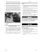
8. See Figure 9. Position the clutch hand lever assembly
inboard of the switch housing assembly engaging the tab
on the lower switch housing in the groove at the bottom
of the clutch lever bracket. Be sure that harness will not
be pinched when installing handlebar clamp. Harness
should reside in recess between handlebar clamp and
clutch lever bracket.
3
2
1
4
is02728
1. Clutch lever bracket
2. Switch housing assembly
3. Groove
4. Tab
Figure 9. Positioning Clutch Lever Bracket with Left
handlebar Switch Housings
9. Align the holes in the handlebar clamp with those in the
clutch lever bracket and start the two screws (with flat
washers) saved from Step 2. Position the assembly for
rider comfort. Beginning with the top screw, tighten the
screws to 60-80 in-lbs (7-9 Nm) using a T27 TORX
®
drive
head.
10. Using a T25 TORX
®
drive head, tighten the lower and
upper switch housing screws to 35-45 in-lbs (4-5 Nm).
NOTE
Always tighten the lower switch housing screw first so that any
gap between the upper and lower housings is at the front of
the switch.
11. Route left hand control harness under handlebar and down
to headlamp area (with nacelle removed). Locate the 8-
place Molex Connector and connect the 6-place control
harness connector.
12. Locate the unused 3-place Molex Connector and connect
the 3-place control harness connector.
13. See Figure 10. Obtain two wire harness retainers (4) from
kit and secure harness to handlebar in two places by
installing barbs on retainers into holes in handlebar.
14. Follow instructions in applicable Service Manual and install
fairing nacelle and windshield.
15. Follow instructions in Service Manual and install left sad-
dlebag, left side cover and air cleaner assembly.
Connect positive (+) battery cable first. If positive (+) cable
should contact ground with negative (-) cable connected,
the resulting sparks can cause a battery explosion, which
could result in death or serious injury. (00068a)
16. Reconnect battery, positive (+) cable first.
17. Install seat.
After installing seat, pull upward on seat to be sure it is
locked in position. While riding, a loose seat can shift
causing loss of control, which could result in death or
serious injury. (00070b)
Cruise Cable Adjustment and Final Test
1. Perform cruise cable adjustment. See "Cable Lash Initial-
ization" in applicable Service Manual.
2. Refer to cruise control section in Owner's Manual for cruise
control operating instructions.
3. Test ride motorcycle and verify cruise control is operating
properly.
-J04167 5 of 6