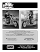
® B9784 B3160 Product features may vary from the picture above. Please read this manual and save it with your original sales receipt. Tools needed for assembly: Phillips Screwdriver, Hammer, Safety Scissors, Slotted Screwdriver and Adjustable Wrench (no tools included). Use only with a Power Wheels® 12 Volt Rechargeable Battery and a Power Wheels® 12 Volt Charger (both included). Sound Box requires three “AA” (LR6) alkaline batteries (batteries not included) for operation.
Table of Contents A B C D E F G H I J K L M N O Important Information . . . . . . . . . . . . . . . . . . . . . . . . . . . . . . . . . . . . . . . . . . . . . . . . . . . . . . . . . . . . . . . . . . . . .2 Warnings and Cautions . . . . . . . . . . . . . . . . . . . . . . . . . . . . . . . . . . . . . . . . . . . . . . . . . . . . . . . . . . . . . . . . . . . .3 Parts . . . . . . . . . . . . . . . . . . . . . . . . . . . . . . . . . . . . . . . . . . . . . . . . . . . . . . . . . . . . . . . . . . . . .
B Warnings and Cautions ELECTRICAL HAZARD WARNING • Battery can fall out and injure a child if vehicle tips over. Always use battery clamp. • PREVENT FIRE - Never modify the electrical system. Alterations could cause a fire resulting in serious injury and could also ruin the electrical system. - Use of the wrong type battery or charger could cause a fire or explosion resulting in serious injury.
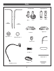
C Parts • If you experience a problem with this product, or are missing a part, please call us at 1-800-348-0751, rather than return this product to the store. • Please identify all parts before assembly and save all packaging material until assembly is complete to ensure that no parts are discarded. • Metal parts have been coated with a lubricant to protect them during shipment. Wipe all metal parts with a paper towel to remove any excess lubricant.
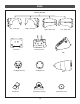
Parts Exhaust Pipe Set Left - Inner Half Front Fork Right - Inner Half Right - Outer Half Left - Outer Half Front Fork Cover Tank Headlight Housing Headlight Lens Seat Sound Box Tachometer Housing 5 Tachometer Cover
Parts Left Shock Set Outer Right Handlebar Inner Inner Outer Left Handlebar Left Strut Signal Lens - 2 Right Shock Set Right Strut Signal Housing - 2 Switch Cover Wire Cover Battery Clamp Handgrip - 2 Wheel Axle - 2 Handlebar Harness Tassel - 2 6 Fork Axle
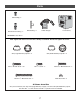
Parts Hex Bushing - 2 Pb 12-VOLT CHARGER Axle Bushing - 2 12 Volt Charger Extended Hex Bushing - 2 12 Volt Battery Not Shown: Label Sheet Note: Tighten and loosen all screws with a Phillips screwdriver. Do not over-tighten the screws. .437 (Large Diameter) Cap Nut - 4* .
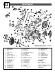
D Parts Diagram 13 20 18 17 13 3 36 20 28 35 37 32 5 34 2 12-VOLT CHARGER 33 27 4 29 15 16 11 26 MT 23 43 31 10 14 9 24 30 12 19 25 38 30 21 14 7 21 40 8 39 22 29 12 41 1. 2. 3. 4. 5. 6. 7. 8. 9. 10. 11. 12. 13. 14. 15 16. 17.
E Battery Charging About Thermal Fuses ELECTRICAL HAZARD Your Power Wheels 12 volt battery is equipped with a built-in thermal fuse. The thermal fuse is a self-resetting safety device which automatically “trips” and shuts down operation of the vehicle if the vehicle is overloaded or the driving conditions too severe. Once a fuse has “tripped”, it will automatically reset itself after approximately 25 seconds and allow the vehicle to resume normal operations.
Battery Charging 1 2 Battery Clamp Battery TM Pb Charger Connector • Plug the charger connector into the battery . • Plug the charger into a standard 120 volt wall outlet . Note: If power flow to the wall outlet is controlled by a switch, make sure the switch is “ON”. • Before first-time use, charge the battery for at least 18 hours. Never charge the battery longer than 30 hours. • Recharge the battery for at least 14 hours after each use of your vehicle. Do not charge the battery longer than 30 hours.
F Assembly Large Rectangular Opening 2 WARNING Children can be harmed by small parts, sharp edges and sharp points in the vehicle’s unassembled state, or by electrical items. Care should be taken in unpacking and assembly of the vehicle. Children should not handle parts, including the battery, or help in assembly of the vehicle.
Assembly 6 4 TM Tab Motor Harness Tab Right Footboard Top View • Fit the motor harness between the vehicle body tabs. 5 • The right footboard was inserted in the vehicle frame at the factory. Make sure the right footboard is in place. • Insert two #8 x 3/ 4" screws into the right footboard as shown. Tighten the screws.
Assembly 8 10 Right Exhaust Pipe Right Exhaust Pipe - Inner Half TM TM * Vehicle Frame • With the holes of both halves aligned, insert six #8 x 3/ 4" screws to join the two halves of the right exhaust pipe. • Tighten the screws. • Repeat steps 7 through 10 to assemble the left exhaust pipe (L) to the left side of the vehicle. Hint: Use a long-shaft Phillips screwdriver to complete this assembly step. • Align the holes in the inner half of the right exhaust pipe with the holes in the vehicle frame.
Assembly 12 Strut 14 Strut Signal Lens Rib Signal Housing Notch Rear Fender #8-32 x 15/ 8" Machine Screw Signal Lens Back View #8-32 x 3/ 4" Machine Screw • Align the rib on the signal lens with the notch in the signal housing. Fit the lens into the housing. • Insert a #8 x 3/ 4" screw into the lens and tighten. • Repeat steps 13 and 14 to assemble the other signal housing and signal lens to the other strut.
Assembly 16 19 Vehicle Frame Axle Bushing Wheel Axle .437" .437 (Large Diameter) Cap Nut Groove Rear Wheel (with Hex Bushings) • Separate the fork axle from the two wheel axles. (The fork axle is shorter than the wheels axles.) Set the fork axle aside for assembly step 39. • Place a .437 (large diameter) cap nut on a flat surface, inside up. Fit the end of a wheel axle into the cap nut. • Tap the opposite end of the wheel axle with a hammer to secure the cap nut on the axle.
Assembly 21 23 Vehicle Frame Neck Lower Hole Front Fork TM Lower Hole Steering Bushing Front Fork Cover Front View • Position the vehicle frame so that the front faces you. • Fit a steering bushing underneath the neck of the vehicle frame. • Insert a #8 x 3/ 4" screw into each end of the steering bushing and tighten. • Fit the front fork into the front fork cover. • Insert two #8 x 1/ 2" screws into the lower holes in the front fork and tighten.
Assembly 27 25 Handlebar Harness Peg Switch Cover Switch Switch Wire Cover Wire Cover Tab Switch Notch • Fit the switch cover peg through the hole in the right handlebar and the switch. • While holding the two parts firmly together, insert two #8 x 3/ 4" screws into the switch and tighten. • Fit the wrapped portion of the handlebar harness into the wire cover. • Fit the tab on the wire cover into the notch in the switch to lock the two parts together.
Assembly 29 Tassel Handgrip 31 Right Handlebar Staple • Using a slotted screwdriver, push the staple in the center of a tassel into the hole in the end of a handgrip. • Repeat this procedure to attach the other tassel to the other handlebar. Handlebar Harness Front Fork 30 Handlebar Harness Plug • While making sure the handlebar harness plug remains inserted through only the upper hole in the front fork, slide the right handlebar down through the upper and lower holes in the front fork.
Assembly 34 33 Left Handlebar Handlebar Harness Front Fork Handlebars • Align the screw holes in each handlebar with the screw holes in the front fork. • First, insert two #8 x 3/ 4" screws through the lower holes in the front fork and into each lower hole in each handlebar and hand tighten. Do not tighten the screws completely. These screws will be tightened in step 54.
Assembly 36 Neck of Vehicle Body 38 Handlebar Harness TM TM See Inset Handlebar Harness Steering Stop Handlebar Assembly Tab • First, fit the tab on the steering stop into the curved slot in the lower steering bushing . • Hold the steering stop in place. • Then, slide the handlebar assembly on the vehicle frame neck and over the steering stop . • Fit the handlebar harness behind the tab in the vehicle frame neck. Tab 37 39 Steering Bushing .354" Fork Axle TM .354 (Small Diameter) Cap Nut .
Assembly 40 41 .354 (Small Diameter) Cap Nut Handlebar Harness Wire Clip TM TM Front Fork Assembly See Inset Fork Axle Handlebar Harness .354" .354 Cap Nut • Insert the handlebar harness into the wire clip on the side of the vehicle body. • Slide the fork axle up through the bottom of the front fork, through the frame neck and steering stop, and out the top of the front fork. • Fit a .354 (small diameter) cap nut on the end of the fork axle.
Assembly 42 Sound Box Buttons 43 Battery Compartment Door Tank Battery Compartment Tabs Sound Box TM 1.5V x 3 “AA” (LR6) SHOWN ACTUAL SIZE • Balance the sound box on the vehicle body. (The speaker should face down.) • Fit the tabs at the bottom of the tank under the front end of the vehicle body. • Lower the tank on the vehicle frame, making sure that the two small square openings in the tank fit over the buttons on the sound box.
Assembly 45 47 PUSH HERE Tachometer Seat Tab Seat Tab Fork Cover Tank Slot TM TM • Fit the tachometer to the fork cover. • Insert two #8 x 3/ 4" screws into the tachometer and tighten. • Fit the tab on the front of the seat into the slot near the tank. • Push down firmly near the back of the seat to “snap” it to the vehicle. Hint: You will need to remove the seat to access the high speed connectors and to charge the 12 volt battery. To remove the seat, press the tab at the back of the seat and lift.
Assembly 49 51 Inner Right Shock Inner Left Shock Extended Hex Bushing Outer Right Shock Outer Left Shock Extended Hex Bushing • The shock sets may be held together by rubber bands to aid in assembly. After completing assembly step 50, remove and throw away the rubber bands. • Fit the inner and outer left shock halves together (they are labeled on the inside with an “L”). Insert a #8 x 3/ 4" screw into the hole in the outer left shock and tighten.
Assembly 53 54 Tighten Screws Shock Tighten Screws .437 (Large Diameter) Cap Nut .437" Wheel Axle .437 Cap Nut • Completely tighten the four screws in the front handlebar assembly to secure the handlebars. • Continue to slide the wheel axle through the extended hex bushing, wheel, extended hex bushing and then the shock. • Fit a .437 (large diameter) cap nut on the end of the wheel axle.
G Label Decoration - Model B3160 Proper label application will help to keep the labels looking their best! When applying labels, keep the following guidelines in mind: • Wash your hands before applying the labels. • Before applying the labels, wipe the surface of the vehicle with a clean, dry cloth to remove any dust or oils. • Place the labels exactly as shown in the illustrations. • For best results, avoid repositioning a label once it has been applied to the vehicle.
Label Decoration - Model B3160 4 18 28 30 7 10 27 Right Side 5 29 19 31 TM 6 13 14 Left Side 27
Label Decoration - Model B9784 Proper label application will help to keep the labels looking their best! When applying labels, keep the following guidelines in mind: • Wash your hands before applying the labels. • Before applying the labels, wipe the surface of the vehicle with a clean, dry cloth to remove any dust or oils. • Place the labels exactly as shown in the illustrations. • For best results, avoid repositioning a label once it has been applied to the vehicle.
Label Decoration - Model B9784 4 18 28 30 6 10 27 Right Side 5 29 19 31 TM 7 13 14 Left Side 29
H Battery Installation IMPORTANT! Use only Power Wheels® 12 volt battery. Use of any other battery will damage your vehicle. Make sure that you charge the battery for at least 18 hours using the enclosed Power Wheels® 12 volt charger before operating your vehicle for the first time. Charge the battery for at least 14 hours after each use of the vehicle. Never charge the battery longer than 30 hours. Failure to follow these instructions may damage your battery and will void your warranty.
I Battery Care and Disposal Battery Care and Disposal Care Disposal If a battery leak develops, avoid contact with the leaking acid and place the damaged battery in a plastic bag. See information below for proper disposal. If acid comes in contact with skin or eyes, flush with cool water for at least 15 minutes and call a physician. If acid is internally ingested, give water, milk of magnesia or egg whites immediately. Never give emetics or induce vomiting. Call a physician.
K Rules for Safe Driving RIDING HAZARD WARNING Prevent Injuries and Deaths • Direct Adult Supervision Required. • Keep Children Within Safe Riding Areas These areas must be: - away from swimming pools and other bodies of water to prevent drownings. - generally level to prevent tipovers. - away from steps, cars, driveways, roads and alleys.
L How to Operate Your Vehicle IMPORTANT! As assembled, your vehicle is ready to roll in low speed (21/2 mph, maximum). When your child is ready to drive the vehicle in high speed (5 mph, maximum), follow the instructions on this page to connect the high speed hook-up and use the power boost button. To Stop Beginner Use - Low Speed Drive • Press the DRIVE button on the tank. • Press the foot pedal. The vehicle drives forward at a maximum of 21/2 mph.
N How to Operate Your Vehicle Advanced Use - High Speed IMPORTANT! Your child should not drive the vehicle in HIGH SPEED from a stopped position. Always start in LOW SPEED. Then, press the power boost button to shift to HIGH SPEED. Power Boost Button • Press the power boost button to shift the vehicle into high speed. The vehicle moves forward at a maximum of 5 mph. • Help your child practice steering to learn how far and how quickly to turn the handlebar when driving forward in high speed.
O Problems and Solutions Guide IMPORTANT! If you experience a problem with your vehicle, first check the Problems and Solutions Guide below. If you still experience a problem, please contact Power Wheels® Consumer Relations, toll-free at 1-800-348-0751 between 8 AM and 6 PM (EST) Monday through Friday. Or, contact your local Power Wheels® authorized service center. For the location nearest to you, please visit us on-line at www.powerwheels.com or call 1-800-348-0751.
Problems and Solutions Guide Problem Vehicle was running but suddenly stopped Short run time (Less than 1 - 3 hours per charge) Possible Cause Solution Loose wire or loose connectors Check all wires and connectors. Make sure the motor harness connector is tightly plugged into the battery, and that there are no loose wires around the motors. Tripped thermal fuse Each Power Wheels® 12 volt battery has a built-in thermal fuse.
Problems and Solutions Guide Problem Vehicle runs sluggishly (cont.) Possible Cause Solution Battery needs charging Be sure to charge the battery after each use. Battery is old and will not accept accept full charge Even with proper care, a rechargeable battery does not last forever. Average battery life is 1 to 3 years depending on vehicle use and use conditions. Replace only with Power Wheels® 12 volt batteries with built-in thermal fuse. Do not substitute parts.
IMPORTANT! DO NOT use this vehicle for the first time until you have charged the battery for 18 hours. Remember to… ✔ Charge the battery immediately after each use. ✔ Charge the battery once a month during storage, even if the vehicle has not been used. Failure to follow these instructions will permanently damage your battery and void your warranty. Please refer to the Battery Care Section in this manual for more information.