
Manual


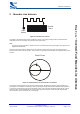
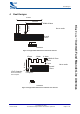


Table Of Contents

Contents
bcant-an-001Pa
© Copyright CSR 2003
This material is subject to CSR’s non-disclosure agreement.
Page 2 of 14
BlueCore
™
Inverted-F and Meander Line Antennas
Contents
1 Introduction.......................................................................................................................................................................3
2 Inverted-F Antenna .........................................................................................................................................................4
3 Meander Line Antenna...................................................................................................................................................5
4 Real Designs.....................................................................................................................................................................6
5 Proximity to Metal Objects...........................................................................................................................................7
6 Proximity to Dielectric Materials.................................................................................................................................8
7 Network Analyser............................................................................................................................................................9
8 Final Tuning...................................................................................................................................................................10
9 Conclusion.....................................................................................................................................................................12
Acronyms and Definitions .................................................................................................................................................13
Record of Changes..............................................................................................................................................................14
List of Figures
Figure 2.1: Inverted-F Antenna...............................................................................................................................................4
Figure 3.1: Meander Line Antenna.........................................................................................................................................5
Figure 3.2: Input Impedance of Two Meander Line Antennas ...........................................................................................5
Figure 4.1: Approximate Dimensions of Inverted-F Antenna.............................................................................................6
Figure 4.2: Approximate Dimensions of Meander Line Antenna.......................................................................................6
Figure 7.1: Preparation Before Measurement......................................................................................................................9
Figure 7.2: Assembled System Ready to Measure.............................................................................................................9
Figure 8.1: Locating Product in Far Field of Antenna....................................................................................................... 10
Figure 8.2: Final Tuning Procedure .................................................................................................................................... 11