
Manual


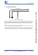
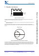


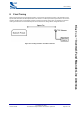
Table Of Contents

Inverted-F Antenna
bcant-an-001Pa
© Copyright CSR 2003
This material is subject to CSR’s non-disclosure agreement.
Page 4 of 14
BlueCore
™
Inverted-F and Meander Line Antennas
2 Inverted-F Antenna
Input
Output
Quarterwave
Figure 2.1: Inverted-F Antenna
The inverted-F is a quarterwave antenna. It is bent into an L-shape. The shorter side is connected to earth. The
longer side is left open circuit at the end. The feed point is located somewhere between the earth end and the
open end. The resulting structure resembles the letter F and possesses the properties of both a loop antenna due
to the circulating current from the feed point to ground and a whip antenna due to the open circuited straight
section.
In the PCB version the antenna is printed on the top layer and a ground plane is placed near the antenna on the
top layer. There must not be a ground plane underneath the antenna.
The aim is to make the quarterwave section resonate at midband frequency (which is 2441MHz for Bluetooth™).
The feed point (which is the input/output connection) is connected to the L-Shape at the point corresponding to
50Ω. Experiment with measurement to determine correct location for the feed point and length of this antenna.