
Manual

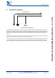
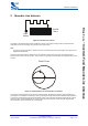
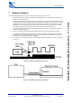
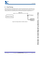
Table Of Contents

Meander Line Antenna
bcant-an-001Pa
© Copyright CSR 2003
This material is subject to CSR’s non-disclosure agreement.
Page 5 of 14
BlueCore
™
Inverted-F and Meander Line Antennas
3 Meander Line Antenna
Input
Output
S
Ground
Plane
Figure 3.1: Meander Line Antenna
The length of the meander line antenna is difficult to predict. It is usually a bit longer than a quarterwave but
dependent on its exact geometry and proximity to the ground plane.
Note:
In Figure 3.1 the ground plane is shown in black. S is the distance from the ground plane. See Figure 4.2 for
approximate dimensions.
This type of antenna is always a PCB version. The antenna is printed on the top layer and a ground plane is
placed near the antenna on the top layer. There must be no ground plane underneath the radiating section of the
antenna.
A
B
Smith Chart
Figure 3.2: Input Impedance of Two Meander Line Antennas
The real part of the impedance of this antenna is about 15-25Ω, depending on geometry and proximity to the
ground plane. The impedance matching is done by adjusting the length of the antenna until the input impedance
is at the unity conductance circle (when normalised to 50Ω), in the top half of the Smith chart (Point A). A shunt
capacitor is then connected between the antenna input and ground to match to 50Ω (Point B). Experimental
measurement is used to determine the correct design.