
Manual
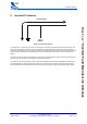
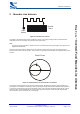
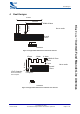
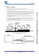
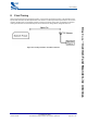
Table Of Contents

Network Analyser
bcant-an-001Pa
© Copyright CSR 2003
This material is subject to CSR’s non-disclosure agreement.
Page 9 of 14
BlueCore
™
Inverted-F and Meander Line Antennas
7 Network Analyser
A Vector Network Analyser (VNA) is used to perform the initial tuning of the antenna:
1. The PCB track (trace), just before the antenna matching network is cut to isolate the filter and previous
stages from the measurement.
2. A coaxial cable is connected between the VNA and the PCB of the product. The outer conductor of the
coaxial cable is soldered to the ground plane of the PCB as close as possible to the input of the antenna
matching network. The inner conductor of the coaxial cable is left floating. The coaxial cable must have
ferrite beads over the outer sleeve of the coaxial cable. The ferrite beads help to prevent RF currents
from flowing on the outside of the coaxial cable (which would disturb the measurement).
3. A One-Port calibration is performed on the VNA with Open, Short, Loads connected at the end of the
coaxial cable inside the product.
4. The inner conductor of the coaxial cable is soldered to the input of the antenna matching network.
5. The antenna is tuned by adjusting the values of any “matching network” components, the feed point of
the antenna or the length of the antenna until the S11 trace (displayed on the VNA) is at the centre of
the Smith chart at the midband frequency 2441MHz.
6. The antenna is now roughly tuned and the cut track can be repaired by putting a small amount of solder
over the cut.
Figure 7.1: Preparation Before Measurement
Figure 7.2: Assembled System Ready to Measure