250 Crossways Park Drive, Woodbury, New York 11797 www.harmankardon.
AVR 100 Audio/Video Receiver OWNER’S MANUAL Volume Speaker Channel Dig. Select Delay COAX DIGITAL SLEEP Power TAPE CD DVD VID 1 VID 2 VID 3 6 CH. AM/FM Set TUNING PRESET SCAN PRESET FM MODE Phones DIGITAL Bass Min Max PRO LOGIC 3-STEREO HALL Treble Min Max THEATER TEST TONE SURR. OFF VIDEO 3 Balance L R L Audio Video ® Version 7 October 5, 1999 Power for the digital revolution.
AVR 100 Audio/Video Receiver 3 4 4 5 7 8 10 13 15 19 19 19 20 21 22 23 23 23 23 24 24 24 24 25 25 25 27 28 30 32 33 34 34 35 Introduction Safety Information Unpacking Front-Panel Controls Front-Panel Information Display Rear-Panel Connections Remote Control Functions Installation and Connections System Configuration Operation Basic Operation Source Selection Surround-Mode Selection Surround-Mode Chart Tuner Operation Tape Recording Output-Level Trim Adjustment 6-Channel Direct Input Memory Backup Programmi
Introduction Thank you for choosing Harman Kardon! With the purchase of a Harman Kardon AVR 100 you are about to begin many years of listening enjoyment. The AVR 100 has been custom designed to provide all the excitement and detail of movie sound tracks and every nuance of musical selections. With onboard Dolby* Digital, the AVR 100 delivers six discrete channels of audio that take advantage of the digital sound tracks from the latest DVD and LD movies and Digital Television (DTV/HDTV) broadcasts.
Safety Information Important Safety Information Verify Line Voltage Before Use Your AVR 100 has been designed for use with 120-volt AC current. Connection to a line voltage other than that for which it is intended can create a safety and fire hazard and may damage the unit. If you have any questions about the voltage requirements for your specific model, or about the line voltage in your area, contact your selling dealer before plugging the unit into a wall outlet.
Front-Panel Controls 36 ˆ ˘ 35 ¸ ¯˜ Volume Speaker Channel Dig. Select Delay COAX DIGITAL SLEEP TAPE CD DVD VID 1 VID 2 VID 3 6 CH. AM/FM Set TUNING PRESET SCAN PRESET FM MODE DIGITAL PRO LOGIC 3-STEREO THEATER HALL TEST TONE SURR.
Front-Panel Controls 8 Video 3 Inputs: These audio/video inputs may be used for temporary connection of video games, camcorders, digital still cameras or portable audio products. To select a source connected to these jacks, press the Vid 3 Input Selector #. 9 Sleep Button: Press this button to place the AVR in the Sleep mode. Once the button is pressed, Information Display 35 will show the time remaining before the unit will automatically go into the Standby mode.
Front-Panel Information Display Q N P O M L J K I H A B C D E F G A Dolby Digital Indicator B Dolby Pro Logic Indicator C Dolby 3 Stereo Indicator D Hall Mode Indicator E Theater Mode Indicator F Optical Source Indicator G Coax Source Indicators H Preset Number I Preset Indicator J Memory Indicator K Stereo Indicator L Mono Indicator M Tuned Indicator N Main Information Display O Mute Indicator P Sleep Mode Indicator Q Night Mode Indicator A Dolby Digital Indicator: This indicator illumina
Rear-Panel Connections ° · R L fi› ‡fl R-AUDIO-L VIDEO 6 C H. ANTENNA ¡ AM LOOP D I R E C T I N REC. OUT FRONT DIGITAL INPUT VIDEO 1 PLAY IN OPTICAL SURR. VIDEO 2 IN SUB WOOFER CENTER DVD IN COAX. 1 ™ CD IN FM 75Ω VIDEO MON. OUT SPEAKERS 8 Ohms AC 120V 60Hz COAX. 2 SWITCHED 100W 1A MAX REC. OUT SUB WOOFER OUT £ TAPE 450W PLAY IN IN ¢ OUT SURR.
Rear-Panel Connections ¡ AM Antenna: Connect the AM loop antenna supplied with the receiver to these terminals. If an external AM antenna is used, make connections to the AM and GND terminals in accordance with the instructions supplied with the antenna. ™ FM Antenna: Connect the supplied indoor or an optional external FM antenna to this terminal. £ Remote IR Input: If the AVR 100’s frontpanel IR sensor is blocked due to cabinet doors or other obstructions, an external IR sensor may be used.
Remote Control Functions NOTE: The function names shown here are each button’s feature when used with the AVR. Most buttons have additional functions when used with other devices. See page 27 for a list of these functions. 37 a VCR V2 DVD V3 INPUT/POWER ON b AM/FM c SOURCE POWER e g OFF d f SLEEP DISC SKIP MODE 35 OFF ON DIM/NIGHT 36 6 CH TAPE CD MAIN POWER 34 SURR.
Remote Control Functions IMPORTANT NOTE: The AVR 100’s remote is shipped from the factory to control all of the functions of the AVR, as well as most Harman Kardon CD, DVD and cassette players. In addition, it may also be programmed to operate many popular VCRs, TV sets, CD and DVD players. Because of the versatility of the remote, each button may have different functions, depending on which product is being controlled.
Remote Control Functions x Direct/Random Buttons: When the AVR’s tuner is in use, press this button to enter a station’s frequency directly into the tuner. After the button has been pressed, press the Numeric Keys o to enter the frequency. When a CD or DVD player is in use, this button is used to activate the Random-Play function. y Slow-Play Buttons: These buttons do not have any function on the AVR but when a DVD is in use they operate the Slow-Play Forward and Reverse functions.
Installation and Connections System Installation After unpacking the unit, and placing it on a solid surface capable of supporting its weight, you will need to make the connections to your audio and video equipment. Audio Equipment Connections We recommend that you use high-quality interconnect cables when making connections to source equipment and recorders to preserve the integrity of the signals.
Installation and Connections System and Power Connections The AVR 100 is designed for flexible use with multiroom systems, external control components and power amplifiers. Remote Control Extension If the receiver is placed behind a solid or smoked-glass cabinet door, the obstruction may prevent the remote sensor from receiving commands. In this event, an optional remote sensor may be used. Connect the output of the remote sensor to the Remote Cont. In jack £.
System Configuration Speaker Selection and Placement The placement of speakers in a multichannel home-theater system can have a noticeable impact on the quality of sound reproduced. No matter which type or brand of speakers is used, the same model or brand of speaker should be used for the front-left, center and front-right speakers.
System Configuration System Setup Once the speakers have been placed in the room and connected, the remaining steps in the setup process are to program the AVR 100’s bass management system for the type of speakers used in your system, calibrate the output levels, and set the delay times used by the surround-sound processor. You are now ready to power up the AVR 100 to begin these final adjustments. 1. Plug the Power Cable ‹ into an unswitched AC outlet. 2.
System Configuration 9. When you have completed your selection for the surround channel, press the Set button t 31 , and then press the ‹/ › buttons r on the remote or the Selector buttons 34 on the front panel to change the display to S-W SPEAKER. 10. Press the Set button t 31 , and then press the ‹/ › buttons r on the remote or the Selector buttons 34 on the front panel to select the option that best describes your system. Select S-W SP YES if a subwoofer is connected to your system.
System Configuration a. When setting the delay time for the Dolby Digital surround modes, the optimal delay time is the result of that subtraction. For example, if the front speakers are ten feet away and the surround speakers are five feet away, the optimal delay time is figured as 10–5=5. Thus, in this example, the delay time for Dolby Digital should be set at five milliseconds. b.
Operation Basic Operation Once you have completed the setup and configuration of the AVR 100, it is simple to operate and enjoy. The following instructions should be followed for you to maximize your enjoyment of your new receiver: • When using the AVR 100 for the first time, you must press the Main Power Switch 1 on the front panel to turn the unit on. This places the unit in a Standby mode, as indicated by the amber color of the Power Indicator 3 .
Operation 3. Within five seconds the AVR will return to normal operation and the unit will now turn on at the same volume level that was in effect when the unit was turned off. Surround-Mode Selection One of the most important features of the AVR 100 is its ability to reproduce a full multichannel surround-sound field from digital sources, analog matrix surround-encoded programs and standard stereo programs. In all, a total of six listening modes is available on the AVR 100.
Operation Surround-Mode Chart MODE FEATURES DELAY TIME RANGE DOLBY DIGITAL Available only with digital input sources encoded with Dolby Digital data. It provides up to five separate main audio channels and a special dedicated Low-Frequency Effects channel. Center: 0 ms – 5 ms Surround: 0 ms – 15 ms DOLBY PRO LOGIC The standard mode for analog surround-sound decoding.
Operation Night Mode A special feature of Dolby Digital is the Night mode, which enables specially encoded input sources to be played back with full digital intelligibility while reducing the minimum peak level by 1/4 to 1/3. This prevents abruptly loud transitions from disturbing others without reducing the impact of the digital source. The Night mode is available only when Dolby Digital signals with special data are being played. connected directly to the digital audio output of your CD or LD player.
Operation • Press and briefly hold the Memory/ Program button w and release it when the MEMORY J and PRESET I indicators begin to flash. • Within three seconds, press the CLEAR button v and hold it until the Main Information Display N reads CLEAR. This will be followed by the preset memory number being cleared. • The tuner will then return to normal operation. • The preset memory number that was cleared is then “empty” and may be left alone or assigned to another station.
Programming the Remote The AVR 100 includes a powerful remote control that is preset to operate all AVR functions and most Harman Kardon products. In addition, the remote contains the codes for most popular brands of audio and video equipment, including DVD and LD players, TV sets and VCRs. Once the remote is programmed with the codes for the equipment in your system, you may eliminate most other remotes, replacing them with of a single, universal remote control.
Programming the Remote For future reference enter the Setup Codes for the equipment in your system here: TV ______________ DVD ____________ CBL ______________ SAT ______________ TV ______________ VCR ______________ Programmed Device Functions Once the AVR 100’s remote has been programmed for the codes of other devices, press the appropriate Device Selector a to change the remote from control over the AVR 100 to the additional product.
Programming the Remote was valid, look at the product being programmed to see if it turns off. 6. If the VCR to be programmed turned off, press the DVD Device Selector a once to complete the process. 7. If the VCR to be programmed does NOT turn off, continue to enter any additional three digit codes for the VCR brand until the VCR turns off. When it does turn off, press the DVD Device Selector a once to complete the process. 8.
Function List No.
Setup Code Tables: TV Manufacturer/Brand Setup Code Number A Mark ADMIRAL AKAI AMSTRAD ANAM AOC BLAUPUNKT BROKSONIC CANDLE CAPEHART CENTRONIC CITIZEN CLASSIC CONCERTO CONTEC CORONADO CRAIG CROWN CURTIS MATHES CXC DAEWOO 094 064 004 049 041 004 077 082 001 055 162 001 041 007 037 122 041 041 004 041 007 102 098 041 059 069 004 157 155 009 029 004 148 007 180 098 181 004 132 111 132 004 015 034 165 041 004 005 122 004 164 064 007 009 001 DAYTRON DYNASTY DYNATECH ELECTROHOME EMERSON ENVISION FISHER FUNAI G
Setup Code Tables: TV (continued) Manufacturer/Brand Setup Code Number MARANTZ MATSUI MEMOREX METZ MGA MINERVA MITSUBISHI NAD NATIONAL NEC OPTONICA ORION PANASONIC PHILCO PHILIPS PIONEER PORTLAND PROSCAN PROTON QUASAR RADIO SHACK RCA REALISTIC RUNCO SAMPO SAMSUNG SANSUI SANYO SCOTT SEARS SHARP SIEMENS SONY SOUNDESIGN SSS SUPRE MACY SYLVANIA SYMPHONIC TANDY TATUNG TECHNICS TECHWOOD TEKNIKA TELERENT TERA THOMSON TMK TOSHIBA TOTEVISION UNIVERSAL VIDEO CONCEPTS VIDTECH WARDS YAMAHA YORK ZENITH 004 132 009 07
Setup Code Tables: VCR Manufacturer/Brand Setup Code Number AIWA AKAI AMPRO AMSTRAD ANAM ASA AUDIO DYNAMICS BROKSONIC CANDLE CANON CAPEHART CITIZEN CRAIG CURTIS MATHES DAEWOO DAYTRON DBX DUAL DYNATECH ELECTROHOME EMERSON 033 017 088 123 030 124 013 034 124 027 086 124 005 030 007 088 013 126 033 055 008 102 126 123 005 033 030 105 013 126 013 006 030 126 030 013 040 013 015 033 014 038 030 013 079 026 030 005 041 014 014 123 024 128 129 FERGUSON FINLUX FISHER FUNAI GE GO VIDEO GOLDSTAR GRAETZ HARMAN KAR
Setup Code Tables: VCR Manufacturer/Brand Setup Code Number NEC NORDMENDE OPTONICA ORION PANASONIC PENTAX PHILCO PHILIPS PILOT PIONEER PORTLAND PULSAR QUARTZ QUASER RADIO SHACK RCA REALISTIC RICO RUNCO SABA SALORA SAMSUNG SANSUI SANYO SCHAUB LORENZ SCOTT SEARS SHARP SHINTOM SONY SOUNDESIGN STS SYLVANIA SYMPHONIC TANDY TASHICO TATUNG TEAC TECHNICS TEKNIKA TELEFUNKEN THOMAS THOMSON THORN TMK TOSHIBA TOTEVISION UNITECH VECTOR RESEARCH VICTOR VIDEO CONCEPTS VIDEOSONIC WARDS YAMAHA ZENITH 013 040 049 135 062
Setup Code Tables: DVD Manufacturer/Brand Setup Code Number CALIFORNIA AUDIO DENON GE GOLDSTAR HARMAN KARDON JVC KENWOOD LOTTE MAGNAVOX MITSUBISHI NAD ONKYO OPTIMUS PANASONIC PIONEER RCA RUNCO SAMSUNG SANYO SHARP SONY TECHNICS THOMSON TOSHIBA YAMAHA 038 005 006 008 001 009 010 011 012 026 013 018 014 027 015 021 030 034 016 024 017 029 006 036 019 32 SETUP CODES 022 007 025 037 028 023 035 031 032 040 039 007 041 020 033 042
Setup Code Tables: LD Players Manufacturer/Brand Setup Code Number CARVER DENON DISCO VISION HITACHI MAGNAVOX MARANTZ MITSUBISHI NAD NEC PANASONIC PHILIPS PIONEER QUASER RCA SAMSUNG SEGA SONY THETA DIGITAL YAMAHA 101 104 106 106 101 102 108 108 109 110 102 106 110 111 103 106 112 107 107 102 105 103 105 107 108 113 114 33 SETUP CODES
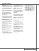
Troubleshooting Guide SYMPTOM CAUSE SOLUTION Unit does not function when Main Power Switch is pushed • No AC Power • Make certain AC power cord is plugged into a live outlet • Check to see if outlet is switch controlled Display lights, but no sound or picture • Intermittent input connections • Mute is on • Volume control is down • Make certain that all input and speaker connections are secure • Press Mute button • Turn up volume control No sound from any speaker; Light around power switch is red •
Technical Specifications Audio Section Stereo Mode Continuous Average Power (FTC) 50 Watts per channel, 20Hz–20kHz, @ < 0.08% THD, both channels driven into 8 ohms Five-Channel Surround Modes Power Per Individual Channel Front L&R channels: 40 Watts per channel, @ < 0.08% THD, 20Hz–20kHz into 8 ohms Center channel: 40 Watts, @ < 0.08% THD, 20Hz–20kHz into 8 ohms Surround channels: 40 Watts per channel, @ < 0.