AVR 1550 Audio/Video Receiver OWNER’S MANUAL ® Power for the Digital Revolution™ Downloaded from www.Manualslib.
Table of Contents 3 4 4 5 7 8 9 11 11 11 12 13 14 14 14 14 14 14 16 16 17 17 19 19 19 19 20 21 21 22 22 22 23 23 23 23 24 24 26 27 27 28 Introduction Safety Information Unpacking Front Panel Controls Front Panel Information Display Rear Panel Connections Remote Control Functions Installation and Connections Audio Equipment Connections Video Equipment Connections SCART A/V Connections Speaker Selection and Placement System Configuration First Turn On Settings to be Made With Each Input Used Input Setup Spea
Introduction Thank you for choosing Harman Kardon! With the purchase of a Harman Kardon AVR 1550 you are about to begin many years of listening enjoyment. The AVR 1550 has been custom designed to provide all the excitement and detail of movie sound tracks and every nuance of musical selections.
Safety Information Important Safety Information Verify Line Voltage Before Use Your AVR 1550 has been designed for use with 220-240-Volt AC current. Connection to a line voltage other than that for which it is intended can create a safety and fire hazard and may damage the unit. If you have any questions about the voltage requirements for your specific model, or about the line voltage in your area, contact your dealer before plugging the unit into a wall outlet.
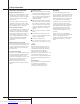
Front Panel Controls ^$# Ô Ó & * ( 1 2 3 1 2 3 4 5 6 7 8 4 5 6 Main Power Switch System Power Control Power Indicator Headphone Jack Remote Sensor Window Tone Mode Surround Mode Selector Tuning 1 Main Power Switch: Press this button to apply power to the AVR 1550. When the switch is pressed in, the unit is placed in a Standby mode, as indicated by the orange LED 3 surrounding the System Power Control 2. This button MUST be pressed in to operate the unit.
Front Panel Controls 7 Surround Mode Selector: Press this button to change the surround mode by scrolling through the list of available modes. Note that Dolby Digital and DTS modes can be selected only when a digital input is used (See page 20 for more information about surround modes.) 8 Tuning Selector: Press the left side of the button to tune lower frequency stations and the right side of the button to tune higher frequency stations.
Front Panel Information Display A B C D E F G Bitstream Indicators Optical Source Indicators DTS Mode Indicator Dolby Digital Indicator Coaxial Digital Input Indicators Dolby Pro Logic II Indicator Analog Input Indicator A Bitstream™ Indicators: When the input is a digital source, one of these indicators will light to display the specific type of signal in use. B Optical Source Indicators: These indicators light to show when a Optical Digital Input has been selected.
Rear Panel Connections ‚ fl ¡ ⁄ Tape Inputs Tape Outputs Video 1 Audio Inputs AM Antenna Video 1 Audio Outputs Video 2 Audio Inputs FM Antenna Tape Inputs: Connect these jacks to the PLAY/OUT jacks of an audio recorder. Tape Outputs: Connect these jacks to the RECORD/INPUT jacks of an audio recorder. Video 1 Audio Inputs: Connect these jacks to the PLAY/OUT audio jacks on a VCR or other video source. AM Antenna: Connect the AM loop antenna supplied with the receiver to these terminals.
Remote Control Functions 0 1 2 3 4 5 6 7 8 9 A B C D E F G H I J K L M N O P Q Power On Button IR Transmitter Window Mute Power Off Button Input Selectors AVR Selector AM/FM Tuner Select Test Button Sleep Button Surround Mode Selector Night Mode Channel Select Button ⁄ / ¤ Buttons ‹ Button Enter Button Digital Select/Direct Button Numeric Keys Tuner Mode Volume Up/Down Tuning Up/Down Speaker Select Transport Controls › Button RDS Select Button Preset Up/Down Clear Button Memory Button Delay b a d f e
Remote Control Functions again to operate the AVR’s functions with the remote. 5 AVR Selector: Pressing this button will switch the remote so that it will operate the AVR’s functions. If the AVR is in the Standby mode, it will also turn the AVR on. 6 AM/FM Tuner Select: Press this button to select the AVR’s tuner as the listening choice. Pressing this button when the tuner is in use will select between the AM and FM bands.
Installation and Connections After unpacking the unit, and placing it on a solid surface capable of supporting its weight, you will need to make the connections to your audio and video equipment. Audio Equipment Connections We recommend that you use high-quality interconnect cables when making connections to source equipment and recorders to preserve the integrity of the signals.
Installation and Connections SCART A/V Connections For the connections described above your video device needs RCA (cinch) connectors or/and S-Video connectors for all Audio and Video signals: Any normal video device (Not SVHS or High 8) for only playback needs 3 RCA jacks, VCRs for record and playback even 6 RCA jacks.
Installation and Connections No matter which type or brand of speakers is used, the same model or brand of speaker should be used at least for the front-left, center and front-right speakers. This creates a seamless front soundstage and eliminates the possibility of distracting sonic disturbances that occur when a sound moves across mismatched front-channel speakers.
System Configuration Once the speakers have been placed in the room and connected, the remaining steps are to program the system configuration memories. With the AVR 1550 two kind of memories are used, those associated individually with the input selected, e.g. surround modes, and others working independently from any input selected like speaker output levels, or delay times used by the surround sound processor. First Turn On You are now ready to power up the AVR 1550 to begin these final adjustments. 1.
System Configuration With the AVR 1550 turned on, follow these steps to configure the speakers: 1. Put the AVR 1550 in the Dolby Pro Logic II Movie mode by pressing the Surround Mode Selector button 7 on the front or 9 and then the ⁄/¤ buttons C on the remote, until DOLBY PRO LOGIC I I MOVIE appears in the Main Information Display M and the PRO LOGIC II indicator F lights. 2. Press the Speaker button K $ on the remote or front panel. The words FNT SPKR will appear in the Main Information Display M. 3.
System Configuration To assist in making these settings, the icons in the Speaker/Channel Input Indicators P will change as the speaker type is selected at each position. When only the inner icon box is lit, the speaker is set for “small.” When the inner box and the two outer boxes with circles inside them are lit, the speaker is set for “large." When no indicator appears at a speaker location, that position is set for “none” or “no” speaker.
System Configuration the optimal delay time is figured as (3–1) x 3+15=21. Thus, in this example, the Pro Logic II delay should be set at twenty milliseconds. NOTE: The DTS, 5CH Stereo, Hall and Theater modes use a fixed, nonadjustable delay time. The Dolby Digital Mode also includes a separate setting for the center channel delay mode, since the discrete nature of these signals makes the location of the center channel speaker more critical.
System Configuration 3. The test noise will immediately begin to circulate in the speakers in a clockwise rotation, pausing at each position for two seconds. As the test noise rotates the speaker positions FL, CEN, FR, SR, SL (Front Left, Center, Front Right, Surround Right, Surround Left) will be shown in the Main Information Display M.
Operation Basic Operation Once you have completed the setup and configuration of the AVR 1550, it is simple to operate and enjoy. The following instructions should be followed for you to maximize your enjoyment of your new receiver: Turning the AVR 1550 On or Off • When using the AVR 1550 for the first time, you must press the Main Power Switch 1 on the front panel to turn the unit on. This places the unit in a Standby mode, as indicated by the orange color of the Power Indicator 3.
Operation Surround Mode Chart MODE FEATURES DELAY TIME RANGE DOLBY DIGITAL Available only with digital input sources encoded with Dolby Digital data. It provides up to five separate main audio channels and a special dedicated Low Frequency Effects channel. Center: 0 ms – 5 ms Initial Setting – 0 ms Surround: 0 ms – 15 ms Initial Setting – 0 ms DTS Available only with digital input sources encoded with DTS data.
Operation Surround Mode Selection One of the most important features of the AVR 1550 is its ability to reproduce a full multichannel surround sound field from digital sources, analog matrix surround encoded programs and standard stereo or even mono programs. In all, a total of eleven listening modes are available on the AVR 1550. Selection of a surround mode is based on personal taste, as well as the type of program source material being used.
Operation PCM Audio Playback PCM (Pulse Code Modulation) is the non- compressed digital audio system used for compact discs, Non-Dolby Digital/DTS Laserdiscs and some special PCM encoded DVDs. The digital circuits in the AVR 1550 are capable of high quality digital-to-analog decoding, and they may be connected directly to the digital audio output of your CD/DVD or LD player (LD only for PCM or DTS programs, for Dolby Digital laser discs an RF adapter is needed, see ”Dolby Digital” above).
Operation IMPORTANT NOTES ON DIGITAL PLAYBACK: 1. When the digital playback source is stopped, or in a pause, fast forward or chapter search mode, the digital audio data will momentarily stop, and the channel position letters inside the Speaker/Channel Indicators P will flash. This is normal and does not indicate a problem with either the AVR 1550 or the source machine. The AVR 1550 will return to digital playback as soon as the data is available and when the machine is in a standard play mode. 2.
Operation Tuner Operation The AVR 1550’s tuner is capable of tuning AM, FM and FM Stereo broadcast stations and receiving RDS data. Stations may be tuned manually, or they may be stored as favorite station presets and recalled from a 30 position memory. Station Selection 1. Press the AM/FM Tuner Select button 6 on the remote to select the tuner as an input.
Operation Program Search (PTY) An important feature of RDS is its capability of encoding broadcasts with Program Type (PTY) codes that indicate the type of material being broadcast.
Function List 1 2 3 4 5 6 7 8 9 10 11 12 13 14 15 16 17 18 19 20 21 22 23 24 25 26 27 28 29 30 31 32 33 34 35 36 37 38 39 40 41 42 43 44 45 46 47 48 49 50 51 52 53 54 55 56 57 58 AVR 1550 26 FUNCTION LIST Downloaded from www.Manualslib.com manuals search engine No.
Troubleshooting Guide SYMPTOM CAUSE SOLUTION Unit does not function when Main Power Switch 1 is pushed • No AC Power • Make certain AC power cord is plugged into a live outlet • Check to see if outlet is switch controlled Display lights, but no sound or picture • Intermittent input connections • Make certain that all input and speaker connections are secure • Press Mute button 2 • Turn up volume control • Mute is on • Volume control is down Sound is heard, but Front-Panel Display does not light •
Technical Specifications Audio Section Stereo Mode Continuous Average Power (FTC) 50 Watts per channel, 20Hz–20kHz, @ < 0.07% THD, both channels driven into 8 ohms Five-Channel Surround Modes Power Per Individual Channel Front L&R channels: 40 Watts per channel, @ < 0.07% THD, 20Hz–20kHz into 8 ohms Center channel: 40 Watts, @ < 0.07% THD, 20Hz–20kHz into 8 ohms Surround channels: 40 Watts per channel, @ < 0.
Downloaded from www.Manualslib.
250 Crossways Park Drive, Woodbury, New York 11797 www.harmankardon.com Harman Consumer International: 2, route de Tours, 72500 Château-du-Loir, France © 2002 Harman Kardon, Incorporated Part No.: 55498730 Downloaded from www.Manualslib.