AVR 1700, AVR 170, AVR 170/230C Audio/video receiver Owner’s Manual
AVR Table of Contents Introduction 3 Set Up the AVR 17 Supplied Accessories 3 Turn On the AVR 17 Important Safety Information 3 Using the On-Screen Menu System 17 Place the AVR 3 Configure the AVR for Your Speakers 17 Front-Panel Controls 4 Assign the AVR INPUT Connectors 18 Rear-Panel Connectors 6 SET UP THE NETWORK 18 System Remote Control Functions 8 Additional Source Setup Menu Items 19 Introduction to Home Theater 10 Operating Your AVR 19 Typical Home The
Introduction IMPORTANT SAFETY INFORMATION Thank you for choosing this Harman Kardon® product! Verify Line Voltage Before Use For more than fifty years, the Harman Kardon mission has been to share a passion for music and entertainment, using leading-edge technology to achieve premium performance. Sidney Harman and Bernard Kardon invented the receiver, a single component designed to simplify home entertainment without compromising performance.
AVR Front-Panel Controls Front-Panel Controls Channel Level Control Button Power Indicator/ Power Button Source Select Buttons IR Sensor Tuning Mode Button/ RDS Button Left/Right Buttons Digital Input Button 4 Set Button Message Display Surround Mode Select Buttons Up/Down Buttons/ Tuning Buttons Surround-Mode Category Button Volume Knob Headphone Jack/ EzSet/EQ Mic Connector Aux Analog Audio Input Connector USB Port
Front-Panel Controls, continued Front-Panel Controls, continued IR sensor: This sensor receives infrared (IR) commands from the remote control. It is important to ensure that the sensor is not blocked. Power indicator/Power button: The AVR has four different power modes: Set button: Press this button to select the currently highlighted menu item.
AVR Rear-Panel Connectors Rear-Panel Connectors HDMI Monitor Out Connector Network Connector Radio Antenna Connectors IR In & Trigger Out Connectors Subwoofer Connector 6 RS-232 Connector HDMI Input Connectors Analog Audio Input/Output Connectors Composite Video Input Connectors Speaker Connectors Digital Audio Input Connectors Composite Video Monitor Output Connectors Main Power Switch AC Input Connector
Rear-Panel Connectors, continued Radio Antenna connectors: Connect the included AM and FM antennas to their respective terminals for radio reception. Analog Audio Input/Output connectors: Use the AVR’s Analog Audio Input/Output connectors for source devices that don’t have HDMI or digital audio connectors. Use the Rec Out connectors to connect to the audio inputs of a VCR or tape deck. See Connect Your Audio and Video Source Devices, on page 13, for more information. Network connector: Use a Cat. 5 or Cat.
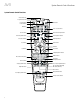
AVR System Remote Control Functions System Remote Control Functions IR Transmitter Lens Program Indicator LED Power On Button Mute Button Power Off Button AVR Button Source Selector Buttons Test Tone Button Channel Up/Down Buttons Tone Controls Button Back Button Channel Volume Adjust Button Volume Up/Down Buttons Delay Adjust Button Options Button OK Button OSD Button Sleep Button Left/Right/Up/Down Buttons Direct Station Entry Button Number Buttons Clear Button Memory Button Tuning Up/Down Butt
System Remote Control Functions, continued System Remote Control Functions, continued Back button: Press this button to return to the previous menu screen when you’re using the on-screen menu (OSD) system. In addition to controlling the AVR, the AVR remote is capable of controlling five other devices, plus your TV and an iPod/iPhone that is docked in the AVR’s front-panel USB port. During the installation process, you may program the codes for each of your source components into the remote.
Introduction to Home Theater and Place Your Speakers AVR Introduction to Home Theater Place Your Speakers This introductory section will help you to familiarize yourself with some basic concepts unique to multichannel surround-sound AVRs, which will make it easier for you to set up and operate your AVR. Determine the locations for your system’s speakers according to their manufacturer’s directions and the layout of your listening room. Use the illustration below as a guide for 5.1-channel systems.
AVR Types of Home Theater System Connections Subwoofer Connections There are different types of audio and video connections used to connect the AVR to your speakers, your TV or video display, and your source devices. The Consumer Electronics Association has established the CEA® color-coding standard. The subwoofer is a speaker dedicated to reproducing only the low (bass) frequencies, which require more power.
Types of Home Theater System Connections, continued AVR Digital Audio Connections – Optical USB Port Optical digital audio connectors are normally covered by a shutter to protect them from dust. The shutter opens as the cable is inserted. Optical input connectors are color-coded using a black shutter. The AVR can play audio files from an Apple iOS® device connected to the USB port, and allows you to control the iOS device via the AVR remote control.
Making Connections Making Connections Connect Your TV or Video Display HDMI Monitor Out connector CAUTION: Before making any connections to the AVR, ensure that the AVR’s AC cord is unplugged from the AVR and the AC outlet. Making connections with the AVR plugged in and turned on could damage the speakers.
AVR Making Connections, continued HDMI devices Optical digital audio devices If any of your source devices have HDMI connectors, using those connectors will provide the best possible video and audio performance quality. Since the HDMI cable carries both digital video and digital audio signals, you do not have to make any additional audio connections for devices you connect via HDMI cables.
Making Connections, continued Audio recorders Connect the Radio Antennas Connect an analog audio recorder’s inputs to the AVR’s analog audio Rec Out connectors. The recorded signal is determined by the source’s Record Out setting in the Source Setup menu. See Additional Source Setup Menu Items, on page 19, for more information. • Connect the supplied FM antenna to the AVR’s FM 75Ω Radio Antenna connector. For the best reception, extend the FM antenna as far as possible.
Making Connections, continued, and Set Up the Remote Control AVR Connect to AC Power 1. Turn on the source device you want to program the remote to control. Connect the AC power cord to the AVR’s AC Input connector and then to a working AC power outlet. 2. Look up the code numbers for the device in Tables A10 – A17 in the Appendix. Write all the applicable code numbers in a convenient place. 3.
Set Up the AVR Set Up the AVR Configure the AVR for Your Speakers Turn On the AVR NOTE: If there are fewer than five main speakers in your system, do not use the EzSet/ EQ process. Instead, proceed as described in Manual Speaker Setup, on page 24. 1. Set the rear-panel Main Power switch to “On.” (The front-panel Power indicator will glow amber.) 2. Press the front-panel Power button. Main Power Switch Power Button 1. Plug the supplied EzSet/EQ microphone into the AVR’s Headphone connector.
AVR Set Up the AVR, continued 8. Select “5.1.” 9. The test will begin. Make sure that the room is quiet while the test noise is playing through the speakers. 10. When the test finishes, press the remote’s OSD button to exit. 6. Select “Audio In” and use the left/right arrow buttons to select the audio input connector you want to assign to the Source button. NOTE: If you have assigned an HDMI Video connector for the Source button you cannot assign a different Audio connector.
c) When you have finished, select “Apply & Save,” and press the OK button. The AVR will refresh the network connection while it remains on. If the AVR cannot connect to the network using the manual settings, contact your ISP or network administrator for assistance. • Proxy Config: If you have connected the AVR’s Network connection to a proxy network, use the Left/Right buttons to set this to “On”, and use the number buttons to enter tne proxy network’s IP address and port.
AVR Operating Your AVR, continued Listening to FM and AM Radio Favorites: To create a Favorites list: Select the Radio source. Use the Tuning Up/Down buttons to tune a station, which will be shown on the front-panel display and the TV screen. 1) Write down your AVR’s MAC Address number, which is found in the Network Setup menu. See Set Up the Network, on page 18, for more information.
Operating Your AVR, continued Playing files on a USB device To share media on PCs: 1. I nsert the USB drive into the AVR’s front-panel USB port. 1. Open Windows Media Player. IMPORTANT: Do not connect a personal computer or peripheral to the USB port. USB hubs are not supported. 2. Open the Library menu and select “Media Sharing.” The Media Sharing window will appear. 2. Select USB as the source device.
Operating Your AVR, continued, and Advanced Functions AVR Listening to Media via AirPlay If you have connected the AVR to a network router that has Wi-Fi® capability, you can wirelessly stream audio to it via AirPlay from compatible Apple devices with iOS 4.2 or newer that are joined on the same Wi-Fi network, and from computers that have iTunes 10.1 or newer that are joined on the same Wi-Fi or wired network.
Advanced Functions Much of the adjusting and configuration your AVR requires is handled automatically, with little intervention required on your part. You can also customize your AVR to suit your system and your tastes. In this section, we will describe some of the more advanced adjustments available to you. Audio Processing and Surround Sound Audio signals can be encoded in a variety of formats that can affect not only the quality of the sound but also the number of speaker channels and the surround mode.
AVR Advanced Functions, continued Dolby Pro Logic II Music Mode Adjustments Step Two – Measure the Speaker Distances When you select Dolby PLII as the music surround mode, additional adjustments become available: Ideally, all of your speakers would be placed in a circle, with the listening position at the center. However, you may have had to place some speakers a little farther away from the listening position than others.
Advanced Functions, continued Crossover Set the Speaker Distances After you return to the Manual Setup menu, navigate to the Crossover line and press the OK button to display the Crossover menu. As described above in Step Two, when you measured the distances from each of your speakers to the listening position, your AVR provides an adjustment that compensates for the different distances so that the sound from each speaker will reach the listening position at the proper time.
AVR To set your levels using the AVR’s internal test tone, select the menu’s Test Tone Seq line and use the Left/Right buttons to select between Auto and Manual. After selecting Auto or Manual, move the cursor to the Test Tone line and use the Left/Right buttons to change the setting to On. Auto: The test tone will automatically circulate to all speakers, as indicated by the highlight bar. Use the Left/Right buttons to adjust the level for any speaker when the test tone is paused there.
Advanced Functions, continued To program punch-through control while operating any device: Sleep Timer 1. For three seconds, press and hold the Source Selector button (or the AVR button) for the main device the remote will be operating. The Program Indicator LED will flash, indicating that the remote is in Program mode and that you may release the button. The sleep timer sets the AVR to play for up to 90 minutes and then turn off automatically. 2. S elect the type of punch-through programming.
AVR Troubleshooting Troubleshooting Symptom Cause Solution Unit does not function when Main Power switch is turned on • No AC power • Ensure that the power cord is plugged into a live AC power outlet • Check if the AC outlet is switch-controlled • Intermittent input connection • Secure all input and speaker connections • Mute is on • Press Mute button • Volume control is turned down • Turn up Volume control • Amplifier is in protection mode due to possible short circuit • Check all speaker
Specifications Specifications Audio Section Stereo power: Multichannel power: Video Section 100W per channel, two channels driven @6/8 ohms, 1kHz, <1.0% THD Television format: NTSC (AVR 1700); PAL (AVR 170/AVR 170/230C) Input level/impedance: 1Vp-p/75 ohms 100 watts per channel two channels driven @ 6/8 ohms, 1 kHz, <1.
AVR Appendix Appendix – Default settings, worksheets, remote product codes Table A1 – Recommended Source Component Connections Device Type AVR Source Default Audio Connection Default Video Connection Cable TV, Satellite, HDTV or other device that delivers television programs Cable/Sat • HDMI 1 Input •H DMI 1 Input DVD player, Blu-ray Disc player Disc • HDMI 2 Input • HDMI 2 Input HDMI-capable music server Server • HDMI 3 Input •H DMI 3 Input HDMI-capable game console Game • HDMI 5
Appendix Table A5 – Speaker/Channel Settings Front Left Front Right Center Surround Left Surround Right Subwoofer ON Number of Speakers Crossover Distance Channel Level Adjust Table A6 – Remote Control Codes Source Selector Connected Device Remote Control Code Cable/Sat TV Disc Server Aux Game STB Audio Table A7 – System Settings Feature Default Setting VFD Fade Time-Out OFF Volume Default OFF Default Vol Set –25dB HDMI Audio to TV OFF Semi-OSD Time-Out 5 Seconds Full-OSD Time-Out 2
AVR Appendix Table A8 – Surround Modes Surround Mode Description Incoming Bitstream or Signal Dolby Digital Provides up to five separate main audio channels and a dedicated low-frequency effects (LFE) channel. • Dolby Digital 1/0/.0 or .1, 2/0/.0 or .1, 3/0/.0 or .1, 2/1/.0 or .1, 2/2/.0 or .1, 3/2/.0 or .1 • Dolby Digital EX (played as 5.
Appendix Table A8 – Surround Modes (cont.) Surround Mode Description Incoming Bitstream or Signal DTS-HD DTS-HD is a high-definition audio format that complements the high-definition video found on Blu-ray Disc and HD-DVD discs. It is transmitted using a DTS core with high-resolution extensions. Even when only DTS 5.1 surround sound is desired (or available, if the multizone system is in use), the higher capacity of high-resolution discs serves up DTS at twice the bit rate used on DVD-Video discs.
AVR Appendix Refer to the numbered buttons when using the Remote Control Function List 34
Appendix Table A9 – Remote Control Function List No.
AVR Appendix Table A9 – Remote Control Function List (cont.) No.
Appendix Table A10 – Remote Control Product Codes: TV TV Manufacturer/Brand Setup Code Number TV Manufacturer/Brand Setup Code Number A MARK 132 122 BRUNS 088 023 ACER 143 167 BUSH 092 043 ADMIRAL 192 105 BUSH (UK) 044 ADVENT 151 CANDLE 128 AIWA 027 110 CAPEHART 059 AKAI 053 093 CELLO 178 182 AKAL 160 123 CENTURION 171 123 AKURA 020 CENTURY 088 023 ALBA 040 CETRONIC 045 AMPRO 164 CGE 105 ANAM 122 112 109 106 045 CIHAN 032 ANSONIC 049 144 145
AVR Appendix Table A10 – Remote Control Product Codes: TV (cont.
Appendix Table A10 – Remote Control Product Codes: TV (cont.
AVR Appendix Table A10 – Remote Control Product Codes: TV (cont.
Appendix Table A10 – Remote Control Product Codes: TV (cont.
AVR Appendix Table A10 – Remote Control Product Codes: TV (cont.) Table A11 – Remote Control Product Codes: DVD (cont.
Appendix Table A12 – Remote Control Product Codes: SAT (cont.
AVR Appendix Table A12 – Remote Control Product Codes: SAT (cont.
Appendix Table A13 – Remote Control Product Codes: Cable (cont.
AVR Appendix Table A15 – Remote Control Product Codes: Music Server (cont.
HARMAN International Industries, Incorporated 8500 Balboa Boulevard, Northridge, CA 91329 USA © 2012 HARMAN International Industries, Incorporated. All rights reserved. Harman Kardon and Logic 7 are trademarks of HARMAN International Industries, Incorporated, registered in the United States and/or other countries. EzSet/EQ is a trademark of HARMAN International Industries, Incorporated. AirPlay, Apple, iPad, iPhone, iPod, iTunes and Mac are trademarks of Apple Inc., registered in the U.S.