® ® Power for the Digital Revolution. AVR 230 AUDIO/VIDEO RECEIVER OWNER’S MANUAL DIGITAL LOGIC 7 PRO LOGIC 3 STEREO DSP 5 CH. STEREO SURR.
AVR 230 AUDIO/VIDEO RECEIVER 3 4 4 5 7 10 13 15 15 15 17 17 18 20 21 21 22 24 24 24 24 24 24 25 26 28 29 29 30 30 30 30 31 32 32 32 32 32 32 33 34 34 34 34 35 36 38 48 48 49 49 Introduction Important Safety Information Unpacking Front-Panel Controls Rear-Panel Connections Main Remote Control Functions Installation and Connections System Configuration Speaker Placement System Setup Input Setup Surround Setup Speaker Setup Delay Settings Output Level Adjustment Using EzSet Manual Output Level Adjustment Oper
INTRODUCTION Thank you for choosing Harman Kardon®! With the purchase of a Harman Kardon AVR 230 you are about to begin many years of listening enjoyment. Designed to provide all the excitement and detail of movie soundtracks and every nuance of musical selections, the AVR 230 is truly a multichannel receiver for the new millennium. The AVR 230 has been engineered so that it is easy to take advantage of all the power of its digital technology.
SAFETY INFORMATION Important Safety Information Verify Line Voltage Before Use Your AVR 230 has been designed for use with 120-volt AC current. Connection to a line voltage other than that for which it is intended can create a safety and fire hazard and may damage the unit. If you have any questions about the voltage requirements for your specific model, or about the line voltage in your area, contact your selling dealer before plugging the unit into a wall outlet.
FRONT-PANEL CONTROLS ¯ ˘ ¸ DIGITAL ˜ ˆ LOGIC 7 PRO LOGIC 3 STEREO DSP 5 CH. STEREO ı VID 1 DVD VID 2 CD VID 3 FMAM VID 4 TAPE 6 8 CH SURR. OFF 1 3 2 5 4 7 6 9 8 !# @) $ ) ( & % ^ Û Ú Ù * Ô Ó Ò NOTE: To make it easier to follow the instructions that refer to this illustration, a larger copy may be downloaded from the Product Support section for this product at www.harmankardon.com.
FRONT-PANEL CONTROLS 8 Surround Mode Selector: Press this button to select from among the available surround mode options for the mode group selected. The specific modes will vary based on the number of speakers available, the mode group and if the input source is digital or analog. For example, press the Surround Mode Group Selector 7 to select a main mode grouping such as Dolby or Logic 7, and then press this button to see the specific mode choices available.
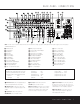
REAR-PANEL CONNECTIONS 37 32 34 36 38 31 33 35 g e c a k i · j h f d b fl ° ‡ ¡ ™ £ ¢ ∞ § ¶ ⁄ ª • ‚ ‹ ¤ fi › NOTE: To make it easier to follow the instructions that refer to this illustration, a larger copy may be downloaded from the Product Support section for this product at www.harmankardon.com.
REAR-PANEL CONNECTIONS • Subwoofer Output: Connect this jack to the linelevel input of a powered subwoofer. If an external subwoofer amplifier is used, connect this jack to the subwoofer amplifier input. ª Front Speaker Outputs: Connect these outputs to the matching + or – terminals on your left and right speakers.
REAR-PANEL CONNECTIONS 36 Video 2 Audio/Video Outputs: Connect the composite or Video and L/R analog audio REC/IN jacks of a VCR or other video recording device such as a DVD recorder or PVR to these jacks. 37 Video 3 Audio/Video Inputs: Connect the composite or Video and L/R analog audio PLAY/OUT jacks of a VCR or other video source to these jacks. 38 AM Antenna Terminals: Connect the AM loop antenna supplied with the receiver to these terminals.
MAIN REMOTE CONTROL FUNCTIONS e f g h ON MUTE OFF TM AVR DVD CD TAPE VCR VID1 TV VID2 CBL/SAT VID3 VID4 DIM AM/FM 6/8 CH SPL TEST T/V 42 41 40 i 39 VOL. NIGHT n q r s TA L 35 LA DE PR EV 1 2 3 4 5 6 7 8 TUN-M 9 0 MEM DIRECT CLEAR t u 34 33 TUNING OSD D.SKIP M2 M3 v PRESET 32 M4 30 31 M1 w o SET p n 36 Y o SP K R m 37 ME N E CH . GU ID l 38 H. k SLEEP CH. SURR. .
MAIN REMOTE CONTROL FUNCTIONS IMPORTANT NOTE: The AVR 230’s remote may be programmed to control up to eight devices, including the AVR 230. Before using the remote, it is important to remember to press the Input Selector Button e that corresponds to the unit you wish to operate. In addition, the AVR 230’s remote is shipped from the factory to operate the AVR 230 and most Harman Kardon CD or DVD players and cassette decks.
MAIN REMOTE CONTROL FUNCTIONS t Direct Button: Press this button when the tuner is in use to start the sequence for direct entry of a station’s frequency. After pressing the button, simply press the proper Numeric Keys r to select a station. (See page 28 for more information on the tuner.) u Tuning Up/Down: When the tuner is in use, these buttons will tune up or down through the selected frequency band.
INSTALLATION AND CONNECTIONS System Installation After unpacking the unit, locating it in a place with adequate ventilation and placing it on a solid surface capable of supporting its weight, you will need to make the connections to your audio and video equipment.
INSTALLATION AND CONNECTIONS Video Equipment Connections Video equipment is connected in the same manner as audio components. Again, the use of high-quality interconnect cables is recommended to preserve signal quality. 1. Connect a VCR’s, personal video recorder’s or other video source’s audio and video Play/Out jacks to the Video 1/Video 2 Audio/Video and/or S-Video Input Jacks eh 33 35 on the rear panel.
SYSTEM CONFIGURATION When all audio, video and system connections have been made, there are a few configuration adjustments that must be made. A few minutes spent to correctly configure and calibrate the unit will greatly add to your listening experience. Speaker Selection and Placement The placement of speakers in a multichannel home theater system can have a noticeable impact on the quality of sound reproduced.
SYSTEM CONFIGURATION 2. Press the Main Power Switch 1 in until it latches and the word “OFF” on the top of the switch disappears inside the front panel. Note that the Power Indicator 2 will turn amber, indicating that the unit is in the Standby mode. 3. Remove the protective plastic film from the frontpanel lens. If left in place, the film will affect the performance of your remote control. 4. Install the three supplied AAA batteries in the remote as shown.
SYSTEM CONFIGURATION To make this process as quick and easy as possible, we suggest that you use the full-OSD system with the on-screen menus, and step through each input. Once you have completed the settings for the first input, many settings may be duplicated for the remaining inputs. It is also a good idea to set the configuration data in the order these items are listed in the MASTER MENU, as some settings require a specific entry in a prior menu item.
SYSTEM CONFIGURATION contains a special “flag” signal in the digital audio data stream, the EX mode will be selected automatically. It may also be selected using this menu or through the front panel or remote controls as shown on page 24. A complete explanation of these modes is found on page 26. When the Dolby Digital mode is selected, there are additional settings available for the Night mode.
SYSTEM CONFIGURATION (Figure 5). If that menu is not already on your screen from the prior adjustments, press the OSD Button v to bring up the MASTER MENU (Figure 1), and then press the ¤ Button n until the cursor is on the SPEAKER SETUP line. At this point, press the Set Button p to bring up the SPEAKER SETUP menu (Figure 5).
SYSTEM CONFIGURATION If the front left/right speakers are set to SMALL, the subwoofer will automatically be set to SUB, which is the “on” position. If the front left/right speakers are set to LARGE, three options are available: • If no subwoofer is connected to the AVR 230, press the ‹ / › Buttons o on the remote so that NONE appears in the on-screen menu. When this option is selected, all bass information will be routed to the front left/right “main” speakers.
SYSTEM CONFIGURATION Delay times are only adjustable for the Dolby modes, so you will notice that the DELAY menu may not be accessed when any other mode, such as a DTS or Logic 7 option, has been selected. In addition, when a non-Dolby Digital mode such as Dolby 3 Stereo or Pro Logic II is selected, adjustments may be made to the Surround speakers only. To set the delay time for a specific input, the DELAY ADJUST menu (Figure 7) should be visible on your on-screen display.
SYSTEM CONFIGURATION 6. During the adjustment, you will see the location of the channel position being adjusted appear in the on-screen display (if connected) and in the Lower Display Line ¯, alternating with a readout of the output setting, relative to the reference volume level, and in the Speaker/Channel Input Indicators ˆ where the letters for the channel being adjusted will flash to indicate the channel from which the test tone should be heard.
SYSTEM CONFIGURATION correct channel from which the test noise should be heard will be shown in the lower third of the video screen and in the Lower Display Line ¯. While the test noise is circulating, the proper channel position will also be indicated in the Speaker/Channel Input Indicators ˆ by a blinking letter within the correct channel. To adjust the output level, press the ⁄/¤ Buttons n until the desired level is shown in the display or on-screen.
OPERATION Basic Operation Once you have completed the initial setup and configuration of the AVR 230, it is simple to operate and enjoy. The following instructions will help you maximize the enjoyment of your new receiver: Turning the AVR 230 On or Off • When using the AVR 230 for the first time, you must first press the Main Power Switch 1 on the front panel to turn the unit on. This places the unit in a Standby mode, as indicated by the amber color of the Power Indicator 2.
OPERATION being used. For example, motion pictures or TV programs bearing the logo of one of the major surroundencoding processes, such as Dolby Surround or DTS Stereo, may be played in either the Dolby Digital, Dolby Pro Logic II Cinema, DTS Neo:6 Cinema, or Logic 7 Cinema surround modes depending on the source material. NOTE: Once a program has been encoded with matrix surround information, it retains the surround information as long as the program is broadcast in stereo.
OPERATION Surround Mode Chart MODE FEATURES Dolby Digital Available only with digital input sources encoded with Dolby Digital data. It provides up to five separate main audio channels and a special dedicated Low-Frequency Effects channel. Dolby Digital EX Available when the receiver is configured for 6.1/7.1-channel operation, Dolby Digital EX is the latest version of Dolby Digital.
OPERATION OPTICAL or COAXIAL inputs, as they appear in the Upper Display Line ˜ or on-screen display. When the digital source is playing, the AVR 230 will automatically detect which type of digital data stream is being decoded and display that information in the Upper Display Line ˜. Digital Bitstream Indications When a digital source is playing, the AVR 230 senses the type of bitstream data that is present. Using this information, the correct surround mode will automatically be selected.
OPERATION has been interrupted. This will happen when a digital input source is selected before the playback starts, or when a digital source such as a DVD is paused. The flashing indicators remind you that the playback has stopped due to the absence of a digital signal and not through any fault of the AVR 230. This is normal, and the digital playback will resume once the playback is started again.
OPERATION • To manually tune through the list of stored preset stations one by one, press the Preset Stations Selector Buttons $ 32 on the front panel or remote. Tape Recording In normal operation, the audio or video source selected for listening through the AVR 230 is sent to the record outputs.
ADVANCED FEATURES The AVR 230 is equipped with a number of advanced features that add extra flexibility to the unit’s operation. While it is not necessary to use these features to operate the unit, they provide additional options that you may wish to use.
ADVANCED FEATURES Full-OSD Time-Out Adjustment The FULL OSD menu system is used to simplify the setup and adjustment of the AVR 230, using a series of on-screen menus. The factory default setting for these menus leaves them on the screen for 20 seconds after a period of inactivity before they disappear from the screen (Time-Out). Time-Out is a safety measure to prevent image retention of the menu text in your monitor or projector, which might happen if it were left on indefinitely.
PROGRAMMING THE REMOTE The AVR 230 is equipped with a powerful remote control that will control not only the receiver’s functions, but also most popular brands of audio and video equipment, including CD players, cassette decks, TV sets, cable boxes, VCRs, satellite receivers and other home theater equipment.
PROGRAMMING THE REMOTE Indicator c will flash green to confirm each button press as you enter commands. NOTE: While entering commands for Power On/Off of any device during a macro sequence, press the Mute Button 42 . DO NOT press the actual Power button. 4. The red LED under the AVR Selector f will go out, and the Program/SPL Indicator c will turn green and flash three times before it goes out. 5. When the Program/SPL Indicator c goes out, the Macro has been erased. 3.
PROGRAMMING THE REMOTE • When a button is pressed on the AVR 230 remote, the red light under the Input Selector ef for the product being operated should flash briefly. If the Device Control Selector flashes for some but not all buttons for a particular product, it does NOT indicate a problem with the remote but rather that no function is programmed for the button being pushed.
PROGRAMMING THE REMOTE Example: To use the TV button to operate a second VCR, first press the TV Input Selector e and the Mute Button 42 at the same time until the red light glows under the TV Button e. Press the VCR Button e, followed by the three-digit code for the specific model you wish to control. Finally, press the TV Button e again.
FUNCTION LIST No.
FUNCTION LIST No. Button Name AVR Function DVD CD/CD-R Tape 45 Tune Up Tune Up Next Chapter Track Direct 46 Direct Direct Tuner Entry Angle Random Play 47 Clear Clear Clear Clear 48 Preset Up Preset Tune Up Slow Forward +10 49 Tune Down Tune Down Prev Chapter Track Increment 50 OSD OSD 51 D.
SETUP CODE TABLE: TV Manufacturer/Brand Setup Code Number AIWA A MARK ADMIRAL AKAI AMPRO ANAM AOC BLAUPUNKT BROKSONIC CANDLE CAPEHART CENTURION CENTRONIC CITIZEN CLASSIC CONCERTO CONTEC CORANDO CORONADO CRAIG CROWN CURTIS MATHES CXC DAEWOO DAYTRON DIGI LINK DYNASTY DYNATECH ELECTROHOME EMERSON FUNAI FUTURETECH GE GOLD STAR/LG GRUNDIG HALL MARK HARMAN KARDON HITACHI INFINITY INKEL JBL JC PENNEY JENSEN JVC KAWASHO KEC KENWOOD KMC KTV LLOYTRON LODGENET 027 122 192 123 164 045 122 084 205 123 059 123 045 045
SETUP CODE TABLE: TV Manufacturer/Brand Setup Code Number LOGIK LUXMAN LXI MAGNAVOX MARANTZ MATSUI MEMOREX METZ MGA MINERVA MITSUBISHI MTC NATIONAL NEC NIKEI ONKING ONWA OPTONICA ORION PANASONIC PHILCO PHILIPS PIONEER PORTLAND PROSCAN PROTON QUASAR RADIO SHACK RCA REALISTIC RUNCO SAA SAMPO SAMSUNG SANYO SCOTT SEARS SHARP SIEMENS SIGNATURE SONY SOUNDESIGN SPECTRICON SSS SYLVANIA SYMPHONIC TANDY TATUNG TECHNICS TECHWOOD 069 128 077 030 115 148 069 084 115 084 077 175 148 115 045 045 045 077 207 087 045 033
SETUP CODE TABLE: TV Manufacturer/Brand Setup Code Number TEKNIKA TELERENT TERA THOMSON TMK TOSHIBA TOTEVISION VIDEO CONCEPTS VIDTECH WARDS YAMAHA YORK YUPITERU ZENITH ZONDA 045 069 156 190 128 063 132 160 128 069 123 128 045 069 122 40 SETUP CODES 069 115 123 191 129 202 128 128 132 090 148 128 132
SETUP CODE TABLE: VCR Manufacturer/Brand Setup Code Number AIWA AKAI AMPRO ASA AUDIO DYNAMICS BROKSONIC CANDLE CANON CAPEHART CITIZEN CRAIG DAEWOO DAYTRON DBX DYNATECH EMERSON FISHER FUNAI GE GO VIDEO GOLD STAR/LG HARMAN KARDON HITACHI JC PENNEY JENSEN JVC KENWOOD LLOYD LXI MAGIN MAGNAVOX MARANTZ MEMOREX MGA MITSUBISHI MULTITECH NAD NATIONAL NEC NORDMENDE OPTIMUS ORION PANASONIC PHILCO PHILIPS PORTLAND PULSAR QUASAR RADIO SHACK RCA REALISTIC 040 048 076 134 018 110 134 135 094 134 045 017 094 018 040 013
SETUP CODE TABLE: VCR Manufacturer/Brand Setup Code Number SALORA SAMSUNG SANSUI SANYO SCOTT SEARS SHARP SONY SOUNDESIGN SYLVANIA SYMPHONIC TANDY TASHICO TATUNG TEAC TEKNIKA THOMAS TiVo TMK TOSHIBA TOTEVISION UNITECH VECTOR RESEARCH VIDEO CONCEPTS VIDEOSONIC WARDS YAMAHA ZENITH 020 045 048 017 110 017 129 080 040 040 040 017 134 048 040 040 040 012 013 112 045 045 018 018 045 040 018 040 42 SETUP CODES 051 095 105 109 116 147 020 112 020 156 129 040 048 155 040 045 112 040 048 050 076 083
SETUP CODE TABLE: CD Manufacturer/Brand ADCOM AIWA AKAI AUDIO TECHNICA AUDIOACCESS AUDIOFILE BSR CALIFORNIA AUDIO CAPETRONIC CARRERA CARVER CASIO CLARINETTE DENON EMERSON FISHER FRABA FUNAI GE GENEXXA GOLD STAR/LG HAITAI HARMAN KARDON HITACHI INKEL JC PENNEY JENSEN JVC KENWOOD LOTTE LUXMAN LXI MAGNAVOX MARANTZ MCINTOSH MCS MITSUMI MODULAIRE NAD NAKAMICHI NEC NIKKO ONKYO OPTIMUS PANASONIC PHILIPS PIONEER PROTON QUASAR RADIO SHACK RCA Setup Code Number 063 069 072 111 118 156 050 177 184 053 125 211 044 109
SETUP CODE TABLE: CD Manufacturer/Brand RCX REALISTIC SANSUI SANYO SCOTT SHARP SHERWOOD SONY SOUNDSTREAM SYMPHONIC TAEKWANG TEAC THETA DIGITAL TOSHIBA VECTOR RESEARCH VICTOR WARDS YAMAHA YORK Setup Code Number 169 058 093 095 104 047 081 134 157 033 082 095 108 058 105 114 151 003 041 058 105 103 115 116 118 124 059 110 177 011 058 085 086 039 013 074 097 151 087 120 130 095 019 031 053 061 166 105 172 108 164 166 159 133 132 167 180 181 139 163 205 206 207 208 106 107 110 121 137 146
SETUP CODE TABLE: SAT Manufacturer/Brand Setup Code Number ALPHASTAR ALPHASTAR DBS ALPHASTAR DSR BIRDVIEW CHANNEL MASTER CHAPARRAL CITOH DRAKE DX ANTENNA ECHOSTAR ELECTRO HOME FUJITSU GENERAL INSTRUMENT HITACHI DBS HOUSTON TRACKER HUGHES JANIEL JERROLD KATHREIN LEGEND MACOM MAGNAVOX MEMOREX NEXTWAVE NORSAT OPTIMUS PACE DSS PANASONIC PANASONIC DBS PANSAT PERSONAL CABLE PHILIPS PICO PRESIDENT PRIMESTAR RCA RCA DSS REALISTIC SAMSUNG SATELLITE SERVICE CO SCIENTIFIC ATLANTA SONY STAR CHOICE DBS STARCAST SUPER
SETUP CODE TABLE: TAPE Manufacturer/Brand HARMAN KARDON Setup Code Number 001 SETUP CODE TABLE: CBL Manufacturer/Brand Setup Code Number ABC ALLEGRO AMERICAST ARCHER BELCOR CABLE STAR CITIZEN COLOUR VOICE DIGI EAGLE EASTERN ELECTRICORD EMERSON FOCUS G.I.
SETUP CODE TABLE: CBL Manufacturer/Brand Setup Code Number REMBRANT SAMSUNG SCIENTIFIC ATLANTA SEAM SIGNATURE SPRUCER STARCOM STARGATE TANDY TELECAPATION TEXSCAN TFC TIMELESS TOCOM UNITED CABLE UNIVERSAL VIDEOWAY VIEWSTAR ZENITH ZENTEK 032 072 183 121 001 053 002 120 024 028 036 122 123 170 011 033 124 019 065 116 186 203 221 222 188 081 177 189 011 163 205 034 039 042 113 211 025 086 089 190 125 211 219 SETUP CODES 47
TROUBLESHOOTING GUIDE SYMPTOM CAUSE SOLUTION Unit does not function when Main Power Switch is pushed • No AC Power • Make certain AC power cord is plugged into a live outlet • Check to see whether outlet is switch-controlled Display lights, but no sound or picture • Intermittent input connections • Make certain that all input and speaker connections are secure • Press Mute Button 42 • Turn up volume control • Mute is on • Volume control is down Unit turns on, but front panel display does not light
AVR 230 TECHNICAL SPECIFICATIONS Audio Section Stereo Mode Continuous Average Power (FTC) 65 Watts per channel, 20Hz–20kHz, @ <0.07% THD, both channels driven into 8 ohms Six-Channel Surround Modes Power per Individual Channel Front L&R channels: 50 Watts per channel @ <0.07% THD, 20Hz–20kHz into 8 ohms Center channel: 50 Watts @ <0.07% THD, 20Hz–20kHz into 8 ohms Surround (L & R Side, L & R back) channels: 50 Watts per channel @ <0.
NOTES 50 NOTES
NOTES NOTES 51
® 250 Crossways Park Drive, Woodbury, New York 11797 www.harmankardon.com © 2003 Harman International Industries, Incorporated Part No.