Audio/video receiver ® Owner’s Manual ENGLISH AVR 1510S, AVR 151S, AVR 151S/230C
AVR Table of Contents INTRODUCTION 3 CONFIGURE THE AVR FOR YOUR SPEAKERS 20 SUPPLIED ACCESSORIES 3 SET UP YOUR SOURCES 22 IMPORTANT SAFETY INFORMATION 3 SET UP THE NETWORK 23 PLACE THE AVR 3 FRONT-PANEL CONTROLS 4 HARMAN REMOTE APP 23 REAR-PANEL CONNECTORS 6 CONTROLLING THE VOLUME 24 8 OPERATING YOUR AVR 23 MUTING THE SOUND 24 10 LISTENING THROUGH HEADPHONES 24 TYPICAL HOME THEATER SYSTEM 10 SELECTING A SOURCE 24 MULTICHANNEL AUDIO 10 SELECTING A SURROUND MODE 24 SURR
Introduction IMPORTANT SAFETY INFORMATION Thank you for choosing this Harman Kardon product! Verify Line Voltage Before Use For more than fifty years, the Harman Kardon mission has been to share a passion for music and entertainment, using leading-edge technology to achieve premium performance. Sidney Harman and Bernard Kardon invented the receiver, a single component designed to simplify home entertainment without compromising performance.
AVR Front-Panel Controls Front-Panel Controls Tuning Mode Button (AVR 1510S)/ RDS Button (AVR 151S) Power Indicator Channel Volume Adjust Button Power Button Set Button IR Sensor Front-Panel Display Volume Knob 1510S Headphone Jack USB Port Left/Right Buttons Audio Input Button 4 Up/Down Buttons/ Tuning Buttons Surround Modes Select Buttons Surround Mode Category Button Source Select Buttons
Front-Panel Controls, continued Power indicator/Power button: The AVR has three different power modes: • Off (Power indicator glows solid amber): The Off mode minimizes energy consumption when you’re not using the AVR. When the AVR is off, it will not automatically turn on or play audio in response to a DLNA DMR stream from a networked device. When the AVR is off, pressing the Power button turns it on. To turn the AVR off when it is on, press the Power button for more than three seconds.
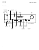
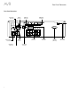
AVR Rear-Panel Connectors Rear-Panel Connectors Digital Audio Connectors Radio Antenna Connectors Analog Audio Connectors 6 Network Connector HDMI Output Connectors HDMI Input Connectors Subwoofer Pre-Out Connector Speaker Connectors IR and Trigger Connectors Analog Video Connectors AC Input Connector (AVR 151S) Power Cord (AVR 1510S)
Rear-Panel Connectors, continued Digital Audio connectors: If your non-HDMI source devices have digital outputs, connect them to the AVR’s digital audio connectors. NOTE: Make only one type of digital connection (HDMI, optical or coaxial) from each device. See Connect Your Audio and Video Source Devices, on page 15, for more information. Radio Antenna connectors: Connect the supplied AM and FM antennas to their respective terminals for radio reception.
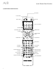
AVR System Remote Control Functions System Remote Control Functions IR Transmitter Power Off Button Mute Button Power On Button Server Source Selector Buttons AVR Button Surround Modes Button OSD/Menu Button OK Button Up/Down/Left/Right Buttons Info/Option Button Back/Exit Button Info/Option Number Buttons Clear Button Test Tone Button Delay Button Sleep Button Channel/Tuner Buttons Volume Up/Down Buttons Tone Tone Button Display Dimmer Button Preset Scan Button RDS Button Direct But
System Remote Control Functions System Remote Control Functions, continued Clear button: Press this button to clear a radio station frequency you have started to enter. In addition to controlling the AVR, the AVR remote is capable of controlling eight other devices, including an iPod/iPhone device connected to the AVR’s front-panel USB port. During the installation process, you may program the codes for each of your source components into the remote.
AVR Introduction to Home Theater and Place Your Speakers Introduction to Home Theater Place Your Speakers This introductory section will help you to familiarize yourself with some basic concepts unique to multichannel surround-sound receivers, which will make it easier for you to set up and operate your AVR. Determine the locations for your system’s speakers according to their manufacturer’s directions and the layout of your listening room. Use the illustrations below as a guide.
AVR Types of Home Theater System Connections Subwoofer Connections There are different types of audio and video connections used to connect the AVR to your speakers, your TV or video display, and your source devices. The Consumer Electronics Association has established the CEA® color-coding standard. The subwoofer is a speaker dedicated to reproducing only the low (bass) frequencies, which require more power.
AVR Types of Home Theater System Connections Digital Audio Connections – Coaxial Radio Connections Coaxial digital audio jacks are usually color-coded in orange. Although they look like standard RCA-type analog jacks, you should not connect coaxial digital audio outputs to analog inputs or vice versa. Your AVR uses separate terminals for the included FM and AM antennas. The FM antenna uses a 75-ohm F-connector. Digital Audio Connections – Optical The AM antenna connector uses spring-clip terminals.
AVR CAUTION: Before making any connections to the audio/video receiver, ensure that the AVR’s AC cord is unplugged from the AC outlet. Making connections with the receiver plugged in and turned on could damage the speakers. Connect Your Speakers Connect Your Subwoofer Use a single RCA audio cable to connect the AVR’s Subwoofer connector to your subwoofer as explained in Subwoofer Connections, on page 11. Consult your subwoofer’s user manual for specific information about making connections to it.
AVR Making Connections Connect Your TV or Video Display If your TV has an HDMI connector and you have HDMI source devices: Use an HDMI cable (not included) to connect it to the AVR’s HDMI Out connector. This will provide the best possible picture quality.
AVR Making Connections Source devices are components where a playback signal originates, e.g. a Blu-ray Disc or DVD player; a cable, satellite or HDTV tuner; etc. Your AVR has several different types of input connectors for your audio and video source devices: HDMI, composite video, optical digital audio, coaxial digital audio and analog audio.
AVR Making Connections Connect Your HDMI Devices Connect Your Optical Digital Audio Devices If any of your source devices have HDMI connectors, using them will provide the best possible video and audio performance quality. Since the HDMI cable carries both digital video and digital audio signals, you do not have to make any additional audio connections for devices you connect via an HDMI cable.
AVR Making Connections Connect the Radio Antennas Use the AVR’s analog audio connectors for source devices that don’t have HDMI or digital audio connectors. AVR Analog Audio Connectors • Connect the supplied FM antenna to the AVR’s FM 75Ω antenna connector. For the best reception, extend the FM antenna as far as possible. • Bend and fold the base of the supplied AM antenna as shown and connect the antenna wires to the AVR’s AM and Gnd connectors. (You can connect either wire to either connector.
AVR Making Connections Connect the Trigger Output If your system has equipment that can be controlled by a DC trigger signal, connect it to the AVR’s Trigger Out connector with a mono 1/8-inch (3.5mm) mini-plug interconnect cable. The AVR will supply a 12V DC (100mA) trigger signal at this connection whenever it is powered on. AVR Mono 1/8-inch (3.
AVR Set Up the Remote Control 2. Look up the code numbers for the device in Tables A10 – A20 in the Appendix. Write all the applicable code numbers in a convenient place. Install the Batteries in the Remote Control 3. Press the Source Selector button for the device and hold it as it glows red, goes dark and glows red again. Then release it. The remote is now in the Programming mode.
AVR Set Up the AVR Set Up the AVR main menu when you press the AVR button. If necessary, reread the Making Connections and Set Up the Remote sections before continuing. In this section, you will configure the AVR to match your actual system’s makeup. Although it’s possible to configure the AVR using only the remote and the messages on the AVR’s front-panel display, it is easier if you use the on-screen menu system. Configure the AVR for Your Speakers Turn On the AVR Press the front-panel Power button.
AVR This selection lets you program the correct setting for each speaker group. The settings in this menu affect the remainder of the speaker setup process and the availability of various surround modes at any time. Select ON when the speakers are present in the system; select OFF for positions where no speakers are installed. The Front Left & Right setting is always ON and may not be disabled.
AVR While making adjustments, you can measure the channel levels in one of these ways: • Preferably, use a handheld SPL meter set to the C-weighting, slow scale. Adjust each speaker so that the meter reads 75dB when the AVR’s built-in test noise is playing. • By ear. Adjust the levels so that the test tone sounds equally loud to you when it plays through each speaker.
AVR If your network uses an automatic IP address, you should not have to perform any network setup procedures. Once you connect the AVR to your home network, the network should automatically assign the AVR an IP address, and the AVR should automatically join your network. If your AVR does not automatically join your network (in which case the AVR will display a “Not Connected” message when you press the Network source button): 1. Press the OSD/Menu button, select System Setup, then select Network. 2.
AVR Operating Your AVR Controlling the Volume Selecting a Surround Mode Adjust the volume either by turning the front-panel Volume knob (clockwise to increase volume or counterclockwise to decrease volume) or by pressing the Volume Up/Down buttons on the remote. The volume is displayed as a negative number of decibels (dB) below the 0dB reference point (–80dB – +10dB). Selecting a surround mode can be as simple or sophisticated as your individual system and tastes.
AVR Listening to FM and AM Radio No other types of media are supported. Select the Radio source. A screen similar to the one in the illustration below will appear. Playing files on a USB device 1. Insert the USB drive into the AVR’s front-panel USB port. IMPORTANT: Do not connect a personal computer or peripheral to the USB port. USB hubs and multi-card readers are not supported. 2. Press the USB source selector button on the remote until the front-panel display’s “USB” as the source.
AVR Operating Your AVR Listening to an iPod/iPhone/iPad Device Listening to vTuner (Internet Radio) When an iPod, iPhone or iPad device is connected to the AVR’s front-panel USB port, you may play audio files through your high-quality audio system, operate the iPod, iPhone or iPad using the AVR remote or the AVR’s front-panel controls and charge the iPod, iPhone or iPad. For the latest compatibility information, please see our Web site: www.harmankardon. com.
AVR To share media on PCs: 1. O pen Windows Media Player. 2. Open the Library menu and select Media Sharing. The Media Sharing window will appear. 3. C heck the “Share My Media” box. An icon for the AVR will appear in the window. 4. S elect the AVR icon, select “Allow,” then select “OK.” The computer’s WMA and MP3 media should now be available to the AVR.
AVR The first number indicates the number of front channels in the signal: “1” represents a monophonic recording (usually an older program that has been digitally remastered or, more rarely, a modern program for which the director has chosen mono as a special effect). “2” indicates the presence of the left and right channels but no center channel. “3” indicates that all three front channels (left, right and center) are present.
AVR System Settings Sleep Timer The AVR’s System Settings menu lets you customize in what way many of the AVR’s features operate. Press the OSD/Menu button and navigate to the System line. Press the OK button to display the System Settings menu. The sleep timer sets the AVR to play for up to 90 minutes and then turn off automatically. Press the Sleep button on the remote, and the time until turn-off will be displayed.
Troubleshooting AVR Symptom Unit does not function Troubleshooting Cause • No AC power Solution • Ensure that the power cord is plugged into a live AC power outlet • Check if the AC outlet is switch-controlled • Intermittent input connection • Secure all input and speaker connections • Mute is on • Press Mute button • Volume control is turned down • Turn up Volume control • Amplifier is in protection mode due to possible short circuit • Check all speaker wires at speaker and AVR conne
AVR Specifications Specifications Audio Section Stereo power: Multichannel power: Frequency range: 520 – 1710kHz (AVR 1510S) 522 – 1620kHz (AVR 151S) 75W per channel, two channels driven @ 6/8 ohms, 1kHz, <0.9% THD Signal-to-noise ratio: 38dB Usable sensitivity (loop): 500µV 75W per channel, two channels driven @ 6/8 ohms, 1kHz, <0.9% THD Distortion (1kHz, 50% mod): 1.
Appendix AVR Appendix Appendix – Default settings, worksheets, remote product codes Table A1 – Recommended Source Component Connections Device Type AVR Source Audio Connection Video Connections Media server Server HDMI 1 HDMI 1 DVD Audio/Video, SACD, Blu-ray Disc, HD-DVD player Disc HDMI 2 HDMI 2 Cable TV, satellite TV, HDTV or other device that delivers television programs Cable/Sat HDMI 3 HDMI 3 DVR or set-top box STB HDMI 4 HDMI 4 Video-game console Game Analog 2 Composite 2 An
AVR Appendix Default Settings Front Left/Right Speakers ON Center Speaker ON Surround Left/Right Speakers ON Subwoofer ON Front Left/Right Speakers Crossover Frequency 100Hz Center Speaker Crossover Frequency 100Hz Surround Left/Right Speakers Crossover Frequency 100Hz Subwoofer Crossover Frequency 100Hz Subwoofer Mode (if Front Speakers are set to Large) Your Settings Position 1 Your Settings Position 2 Your Delay Settings Position 1 Your Delay Settings Position 2 ENGLISH Table A2 –
AVR Appendix Table A4 – Source Settings Cable/ Sat Disc Server Radio TV / iPod/ USB Network vTuner Game AUX STB Connected Device Surround Mode Video Input N/A N/A N/A N/A Audio Input Radio HDMI ARC/ Optical USB Network Night Mode N/A N/A N/A Adjust Lip Sync N/A N/A N/A Change Name N/A N/A N/A N/A Bass Treble Table A5 – Dolby Pro Logic II Music Settings Default Settings Center Width 3 Dimension 0 Panorama Off 34 Your Settings Audio
AVR Table A6 – Remote Control Codes Source Input Appendix Device Type (if changed) Product Brand and Code Number ENGLISH Cable/Sat Disc DVR Media Server TV Game AUX Table A7 – System Settings Feature Default Panel Timeout Off Auto Power Off 8 hours Menu Timeout Off Status Message 5 seconds Volume Default Off Default Volume Setting Your Settings –25dB HDMI Audio to TV Off HDMI Link Off 35
AVR Appendix Table A8 – Surround Modes Surround Mode Dolby Digital Description Provides up to five separate main audio channels and a dedicated low-frequency effects (LFE) channel. Incoming Bitstream or Signal • Dolby Digital 1/0/.0 or .1, 2/0/.0 or .1, 3/0/.0 or .1, 2/1/.0 or .1, 2/2/.0 or .1, 3/2/.0 or .1 • Dolby Digital EX (played as 5.1) • Dolby Digital Plus decoded and delivered via coaxial or optical connection Dolby Digital EX An expansion of Dolby Digital 5.
AVR Appendix Table A8 – Surround Modes – continued Virtual speaker Description Simulates 5.1 channels when only two speakers are present or a more enveloping sound field is desired. Incoming Bitstream or Signal ENGLISH Surround Mode • Dolby Digital • Analog (two-channel) • Tuner • PCM (32kHz, 44.1kHz or 48kHz) DTS Digital Using a different encoding/decoding method than Dolby Digital, DTS Digital also provides up to five discrete main channels, plus an LFE channel. • DTS 1/0/.0 or .1, 2/0/.0 or .
AVR Appendix Table A8 – Surround Modes – continued Surround Mode Description Incoming Bitstream or Signal DTS Neo:6 Mode Group DTS Neo:6 analog processing is available with DTS and DTS 96/24 signals and two-channel analog or PCM signals to create a 3-, 5- or 6-channel presentation. See below DTS Neo:6 Cinema Depending on the number of speakers in your system, select 3-, 5- or 6-channel modes, enhanced for movie or video presentations. • DTS 2/2/.0 or .1, 3/2/.0 or .
AVR ENGLISH Appendix Server Info/Option Refer to the numbered buttons when using the Function List in Table A9.
AVR Appendix Table A9 – Remote Control Function List Radio No.
AVR Appendix Table A9 – Remote Control Function List – continued Button Name Cable/Sat Game 01 02 03 04 05 06 07 08 09 10 11 12 13 14 15 16 17 18 19 20 21 22 23 24 25 26 27 28 29 30 31 32 33 34 35 36 37 38 39 40 41 42 43 44 45 46 47 48 49 50 51 52 53 54 55 56 AVR Power On AVR Power Off Mute Cable/Sat STB TV Disc Server Aux Device Power On Device Power Off AVR Mute Input Sel Input Sel Input Sel Input Sel Input Sel Input Sel Input Sel Input Sel Input Sel Input Sel Input Sel Input Sel Surround Modes Men
AVR Appendix Refer to Tables A10 through A20 when programming the codes for your components into the remote.
AVR Table A11 – Remote Control Product Codes: AUX-HDTV VCR Manufacturer/Brand Setup Code Number 439 TV Manufacturer/Brand Setup Code Number NAD APEX 614 616 NATIONAL 440 DISH NETWORK 612 NEC 318 348 LG 604 NORDMENDE 348 607 608 609 610 611 OPTIMUS 459 MOTOROLA 605 ORION 447 RCA 601 612 PANASONIC 425 450 467 472 SAMSUNG 603 PHILCO 340 618 PHILIPS 340 375 TIVO See Table A24 PORTLAND 394 ZENITH 602 606 619 PULSAR 376 QUASAR 301 425 RADIO SHACK 355 434 440 442 458
AVR Appendix Table A13 – Remote Control Product Codes: AUX-CD CD Manufacturer/Brand Setup Code Number CD Manufacturer/Brand Setup Code Number RCA 024 081 093 150 ADCOM 063 069 REALISTIC 058 093 095 104 105 108 164 166 AIWA 072 111 118 156 170 SANSUI 047 081 134 157 172 AKAI 050 177 184 SANYO 033 082 095 AUDIO TECHNICA 053 SCOTT 108 AUDIOACCESS 125 SHARP 058 105 114 151 159 167 180 181 AUDIOFILE 211 SHERWOOD 003 041 058 105 133 BSR 044 SONY 103 115 116 118 132 139 163 205 20
AVR Appendix Table A16 – Remote Control Product Codes: Game SAT Manufacturer/Brand Setup Code Number GAME Manufacturer/Brand Setup Code Number BIRDVIEW 425 Microsoft (XBOX, XBOX 360) 001 003 CHANNEL MASTER 320 321 325 361 NYKO (PS3) 005 CHAPARRAL 315 316 451 SONY (PS2, PS3) 002 004 CITOH 360 DIRECTV 309 310 314 DISH NETWORK 364 DRAKE 313 317 318 413 481 DX ANTENNA 331 352 379 483 ABC 001 011 ECHOSTAR 364 395 397 452 453 463 477 478 484 485 ALLEGRO 111 392 AMERICAST 212 3
AVR Appendix Table A17 – Remote Control Product Codes: Cable – continued Table A20 – Remote Control Product Codes: AUX- TiVo Cable Manufacturer/Brand Setup Code Number Manufacturer/Brand Setup Code Number STARCOM 002 011 163 COMCAST TIVO 808 STARGATE 120 COX TIVO 808 024 DIRECTV TIVO 806 TELECAPATION 028 HUMAX TIVO 803 TEXSCAN 036 Nero LiquidTV TIVO 805 TFC 122 PIONEER TIVO 801 TIVO 029 030 and See Table A24 TIVO HD XL DVR 807 170 205 TIVO HD DVR 804 UNITED CABLE 011 T
ENGLISH AVR 47
HARMAN International Industries, Incorporated 8500 Balboa Boulevard, Northridge, CA 91329 USA © 2015 HARMAN International Industries, Incorporated. All rights reserved. Harman Kardon is a trademark of HARMAN International Industries, Incorporated, registered in the United States and/or other countries. Other trademarks and trade names are those of their respective owners. Apple, iPhone, iPod and iTunes are trademarks of Apple Inc., registered in the U.S. and other countries.