AVR 3000 Audio/Video Receiver OWNER’S MANUAL AVR 3000 ® Power for the Digital Revolution™
Table of Contents 3 4 4 5 7 9 11 14 14 14 15 16 17 17 18 19 19 19 21 21 21 22 22 23 23 25 25 25 25 26 27 27 29 30 30 30 31 32 34 34 34 35 35 36 36 37 38 38 39 39 39 40 42 50 50 51 Introduction Safety Information Unpacking Front Panel Controls Front Panel Information Display Rear Panel Connections Remote Control Functions Installation and Connections Audio Equipment Connections Video Equipment Connections SCART A/V Connections System and Power Connections System Configuration Speaker Selection and Placement
Introduction Thank you for choosing Harman Kardon! With the purchase of a Harman Kardon AVR 3000 you are about to begin many years of listening enjoyment. The AVR 3000 has been custom designed to provide all the excitement and detail of movie sound tracks and every nuance of musical selections.
Safety Information Important Safety Information Verify Line Voltage Before Use Your AVR 3000 has been designed for use with 220-240-Volt AC current. Connection to a line voltage other than that for which it is intended can create a safety and fire hazard and may damage the unit. If you have any questions about the voltage requirements for your specific model, or about the line voltage in your area, contact your dealer before plugging the unit into a wall outlet.
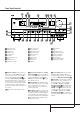
Front Panel Controls ˆ 29 Ù ı Û Ú Ò Ô Ó AVR 3000 RDS PTY CT RT TA ( * & ^ RDS 1 2 3 4 5 6 7 8 9 ) ! @ $ # % 1 Main Power Switch 2 System Power Control 3 Power Indicator 4 Headphone Jack 5 Selector Buttons 6 Tone Mode 7 Surround Mode Selector 8 Tuning 9 Tuner Band Selector ) Preset Stations Selector ! Input Source Selector @ RDS Select Button # Digital Optical 3 Input $ Digital Coax 3 Input % Video 4 input jacks ^ Bass Control & Balance Control * Treble Control ( Volume Control Ó Set
Front Panel Controls 7 Surround Mode Selector: Press this button to change the surround mode by scrolling through the list of available modes. Note that Dolby Digital and DTS modes can be selected only when a digital input is used (See page 26 for more information about surround modes.) 8 Tuning Selector: Press the left side of the button to tune lower frequency stations and the right side of the button to tune higher frequency stations.
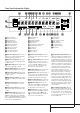
Front Panel Information Display A DTS DOLBY D PCM MP3 B P AE AD YAC AB AA X W V MUTE RDS CT RT TA AUTO TUNED ST MEMORY PRESET SLEEP Q O O L 0 C 0 R O O O OPTICAL 1 2 3 C A B C D E F G H I J K PTY U TSR COAXIAL 1 2 3 DIGITAL PRO LOGIC D E F Bitstream Indicators Optical Source Indicators DTS Mode Indicator Dolby Digital Indicator Coaxial Source Indicators Dolby Pro Logic Indicator Analog Input Indicator Dolby 3 Stereo Indicator VMAx Mode Indicator 5 Channel Stereo Indicator Logic
Front Panel Information Display S Preset Indicator: This indicator lights when the tuner is in use to show that the Preset Number/Sleep Timer R is showing the station’s preset memory number. (See page 31 for more information on tuner presets.) T Sleep Indicator: This indicator lights when the Sleep function is in use. The numbers in the Preset/Sleep Number Indicators will show the minutes remaining before the AVR 3000 goes into the Standby mode. (See page 25 for more information on the Sleep function.
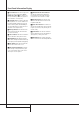
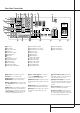
Rear Panel Connections k f 31 L R d b L VIDEO R · c ih g e j a ° AC INPUT S-VIDEO ~230V/50HZ A ¡ VID 3 IN VID 3 1 TAPE ™ OPT OUT IN IN REMOTE 2 £ ANTENNA VID 2 VID 2 OUT OUT MODEL NO. AVR 3000 IN 1 NORTHRIDGE CALIFORNIA, USA OUT COAX IN AM ¢ § IN MADE IN CHINA 2 VID 1 ∞ ¶ VID 1 DIGITAL IN OUT GND OUT AC OUTLETS ~230V/50Hz OPT FM 75Ω DVD UNSWITCHED / 100W MAX DVD COAX • DIGITAL OUT CENTER SL + + MON.
Rear Panel Connections Video Monitor Outputs: Connect these jacks to the composite and/or S-Video input of a TV monitor or video projector to view the onscreen menus and the output of any video source selected by the receiver’s video switcher. Remote IR Input: If the AVR 3000’s frontpanel IR sensor is blocked due to cabinet doors or other obstructions, an external IR sensor may be used. Connect the output of the sensor to this jack.
Remote Control Functions b a c h POWER d OFF TM 38 ON e f AVR DVD CD TAPE VCR TV VID2 CBL/SAT VID3 VID4 AM/FM 6 CH. SPL VID1 g 37 36 i j k 35 SLEEP PR SURR. TEST VOL. NIGHT l 32 n o 31 SET p q AY L DE n s NO 1 2 3 4 5 6 7 8 TUN-M 9 0 MEM t 29 28 u v 30 RM AL TA L r 33 ME N R CH .
Remote Control Functions IMPORTANT NOTE: The AVR 3000’s remote may be programmed to control up to seven devices, including the AVR 3000. Before using the remote, it is important to remember to press the Input Selector button 4 that corresponds to the unit you wish to operate. In addition, the AVR 3000’s remote is shipped from the factory to operate the AVR 3000 and most Harman Kardon CD or DVD players and cassette decks.
Remote Control Functions J Direct Button: Press this button when the tuner is in use to start the sequence for direct entry of a station’s frequency. After pressing the button simply press the proper Numeric Keys H to select a station (See page 31 for more information on the tuner). Q Preset Up/Down: When the tuner is in use, press these buttons to scroll through the stations programmed into the AVR 3000’s memory.
Installation and Connections After unpacking the unit, and placing it on a solid surface capable of supporting its weight, you will need to make the connections to your audio and video equipment. Audio Equipment Connections We recommend that you use high-quality interconnect cables when making connections to source equipment and recorders to preserve the integrity of the signals.
Installation and Connections SCART A/V Connections For the connections described above your video device needs RCA (cinch) connectors or/and SVideo connectors for all Audio and Video signals: Any normal video device (Not SVHS or High 8) for only playback needs 3 RCA jacks, VCRs for record and playback even 6 RCA jacks. Any S-Video device (SVHS, High 8) needs 2 RCA (Audio) and 1 S-Video jack (Video), if it´s a playback unit, or 4 RCA (Audio In/Out) and 2 S-Video (Video In/Out) jacks, if it´s a recording VCR.
Installation and Connections System and Power Connections The AVR 3000 is designed for flexible use with external control components and power amplifiers. Remote Control Extension If the receiver is placed behind a solid or smoked glass cabinet door, the obstruction may prevent the remote sensor from receiving commands. In this event, the remote sensor of any Harman Kardon or other compatible device, not covered by the door, or an optional remote sensor may be used.
System Configuration Speaker Selection No matter which type or brand of speakers is used, the same model or brand of speaker should be used for the front-left, center and front-right speakers. This creates a seamless front soundstage and eliminates the possibility of distracting sonic disturbances that occur when a sound moves across mismatched front-channel speakers.
System Configuration First Turn On and Use of the OSD Once the speakers have been placed in the room and connected, the remaining steps are to program the system configuration memories. With the AVR 3000 two kind of memories are used, those associated individually with the input selected, e.g. surround modes, and others working independently from any input selected like speaker output levels, or delay times used by the surround sound processor.
System Configuration Input Setup The first step in configuring the AVR 3000 is to select an input. This may be done by pressing the front panel Input Source Selector ! until the desired input’s name appears momentarily in the Main Information Display Y, and the green LED lights next to the input’s name in the front panel Input Indicators Ô. The input may also be selected by pressing the appropriate Input Selector on the remote control 46.
System Configuration you are in doubt as to which category describes your speakers, consult the specifications in the speakers’ owner’s manual, or ask your dealer. Remember that the speaker setup must be made individually for each input of the AVR 3000. It is best to select the Dolby Pro Logic mode for making the speaker setup.
System Configuration Making Settings independent of selected Input Within five seconds, either press the front panel ‹/› Selector buttons 5 or the ⁄/¤ buttons D on the remote to select a different speaker position, or press the Set Button ÓF to begin the adjustment process for the front left and right speakers When the Set button Ó F has been pressed and the system is ready for a change to the front speaker setting, the on-screen display and Main Information Display Y will read F N T LARGE or F N T SMALL d
System Configuration Logic delay should be set at twenty milliseconds. NOTE: The DTS, Logic 7, 5CH Stereo, Hall and Theater modes use a fixed, nonadjustable delay time. The Dolby Digital Mode also includes a separate setting for the center channel delay mode, since the discrete nature of these signals makes the location of the center channel speaker more critical.
System Configuration Using EzSet Harman Kardon’s exclusive EzSet remote makes it possible to quickly and accurately set the AVR 3000’s output levels without the use of a sound pressure meter, although manual adjustment is also available. However, for the easiest set-up, follow these steps while seated in the listening position that will be used most often: 8.
System Configuration Continue to adjust the individual speakers until they all have the same volume. Note that adjustments should be made with the ‹/› buttons E! on the remote only, NOT the main volume controls. You may also adjust the output levels manually while using the level indication feature of the EzSet remote. To activate the sensor and indicator, simply press and release the SPL Indicator Select button & on the remote while the test tone is circulating.
Operation Basic Operation Once you have completed the setup and configuration of the AVR 3000, it is simple to operate and enjoy. The following instructions should be followed for you to maximize your enjoyment of your new receiver: Turning the AVR 3000 On or Off • When using the AVR 3000 for the first time, you must press the Main Power Switch 1 on the front panel to turn the unit on. This places the unit in a Standby mode, as indicated by the amber color of the Power Indicator 3.
Operation Surround Mode Chart MODE FEATURES DELAY TIME RANGE DOLBY DIGITAL Available only with digital input sources encoded with Dolby Digital data. It provides up to five separate main audio channels and a special dedicated Low Frequency Effects channel. Center: 0 ms – 5 ms Initial Setting – 0 ms Surround: 0 ms – 15 ms Initial Setting – 0 ms DTS Available only with digital input sources encoded with DTS data.
Operation Surround Mode Selection One of the most important features of the AVR 3000 is its ability to reproduce a full multichannel surround sound field from digital sources, analog matrix surround encoded programs and standard stereo or even mono programs. In all, a total of thirteen listening modes are available on the AVR 3000. Selection of a surround mode is based on personal taste, as well as the type of program source material being used.
Operation or a PCM audio track from DVD, use the Logic 7 C or Cinema mode. For stereo or surround encoded pure music recordings use the Logic 7 M or Music mode for a wider front sound stage (see Surround Mode Chart page 26). MP3 Audio Playback The AVR 3000 is one of the first A/V receivers to provide on-board decoding for the MP3 audio format used on specific computer audio files and by portable MP3 players/recorders.
Operation is important to note that although Dolby Digital, for example, is referred to as a “5.1” system, not all Dolby Digital DVD or audio tracks selected on DVD or other Dolby Digital programs are encoded for 5.1. Thus, it is sometimes normal for a DVD with a Dolby Digital soundtrack to trigger e.g. only the “L” and “R” indicators. NOTE: Many DVD discs are recorded with both “5.1” and “2.0” versions of the same soundtrack, the ”2.0” version often is used with other languages.
Operation Output Level Trim Adjustment Normal output level adjustment for the AVR 3000 is established using the test tone, as outlined on pages 22 and 23. In some cases, however, it may be desirable to adjust the output levels using program material such as a test disc, or a selection you are familiar with. Additionally, the output level for the subwoofer and those for the Stereo and VMAx modes can only be adjusted using this procedure.
Operation Tuner Operation The AVR 3000’s tuner is capable of tuning AM, FM and FM Stereo broadcast stations and receiving RDS data. Stations may be tuned manually, or they may be stored as favorite station presets and recalled from a 30 position memory. Station Selection 1. Press the AM/FM Tuner Select button 6 on the remote to select the tuner as an input.
Operation RDS Operation The AVR 3000 is equipped with RDS (Radio Data System), which brings a wide range of information to FM radio. Now in use in many countries, RDS is a system for transmitting station call signs or network information, a description of station program type, text messages about the station or specifics of a musical selection, and the correct time.
Operation • JAZZ: Jazz Music • COUNTRY: Country Music • NATIONAL: National Music • OLDIES: Oldies Music • FOLK M: Folk Music • DOCUMENT: Documentary Programs • TEST: Emergency Test NOTE: Many stations do not transmit a specific PTY. The display will show NONE, when such a station is selected and PTY is active. NOTE: Some stations transmit constant traffic information. To identify as traffic station, they transmit a specific traffic code constantly, which causes the TA Indicator AA to light in the display.
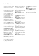
Advanced Features The AVR 3000 is equipped with a number of advanced features that add extra flexibility to the unit’s operation. While it is not necessary to use these features to operate the unit, they provide additional options that you may wish to use. Display Brightness The AVR 3000’s front panel Main Information Display Ú is set at a default brightness level that is sufficient for viewing in a normally lit room.
Advanced Features Semi-OSD Settings The semi-OSD system places one line messages at the lower third of the video display screen whenever the Volume, Input Source, Surround mode or tuner frequency of any of the configuration settings are changed. The semi-OSD system is helpful in that enables you to have feedback on any control changes or remote commands using the video display when it is difficult to view the front-panel displays.
Programming the Remote The AVR 3000 is equipped with a powerful remote control that will control not only the receiver’s functions, but also most popular brands of audio and video equipment, including CD players, TV sets, cable boxes, VCRs, satellite receivers and other home-theater equipment. Once the AVR 3000’s remote is programmed with the codes for the products you own, it is possible to eliminate most other remotes and replace them with the convenience of a single universal remote control.
Programming the Remote Macro Programming Macros enable you to easily repeat frequently used combinations of commands with the press of a single button on the AVR 3000’s remote control. Once programmed, a macro will send out up to 19 different remote codes in a pre-determined sequential order enabling you to automate the process of turning on your system, changing devices, or other common tasks.
Programming the Remote Programmed Device Functions Once the AVR 3000’s remote has been programmed for the codes of other devices, press the appropriate Input Selector 4 to change the remote from control over the AVR 3000 to the additional product. When you press any of these buttons, it will briefly flash in red to indicate that you have changed the device being controlled.
Programming the Remote Channel Control Punch-Through Transport Control Punch-Through Resetting the Remote Memory The AVR 3000’s remote may be programmed to operate so that the channel control function for either the TV, cable or satellite receiver used in your system may be used in conjunction with one of the other devices controlled by the remote.
Function List 2 1 3 4 5 6 7 8 9 10 11 12 13 14 15 16 17 18 19 20 21 22 25 23 24 26 28 27 30 31 29 34 33 32 35 36 37 38 39 40 41 42 43 44 45 46 47 48 49 50 51 52 53 54 55 56 57 58 59 60 61 62 63 3000 40 FUNCTION LIST No.
Function List No. Button Name Tape VCR (VID 1) TV (VID 2) CBL (VID 3) SAT(VID 3) 1 2 3 4 5 6 7 8 9 10 11 12 13 14 15 16 17 18 19 20 21 22 23 24 25 26 27 28 29 30 31 32 33 34 35 36 37 38 39 40 41 42 43 44 45 46 47 48 49 50 51 52 53 54 55 56 57 58 59 60 61 62 63 Power Off Power On Mute AVR DVD CD Tape VID 1 VID 2 VID 3 VID 4 AM/FM 6 Ch.
Setup Code Table: TV Maker (Brand) Name AIWA AKAI ALBA ARC EN CIEL ARCAM BANG & OLUFSEN BEKO BLAUPUNKT BRANDT ELECTRONIQUE BRION VEGA BRUNS BUSH BUSH(UK) CGE DAEWOO DECCA(UK) DUMONT DUMONT-FINLUX DYNATRON ELBE EMERSON FERGUSON FIDELITY(UK) FINLANDIA FINLUX GEC(UK) GOLDSTAR GOODMANS GORENJE GRANADA GRANADA(UK) GRUNDIG HANSEATIC HIFIVOX HITACHI IMPERIAL INTERFUNK INTERVISION ITT ITT-NOKIA JVC KARCHER KATHREIN KORTING LOEWE LOEWE OPTA LUXOR MAGNADYNE MARANTZ MARELLI METZ MINERVA MITSUBISHI NATIONAL 42 SETUP C
Setup Code Table: TV (continued) Maker (Brand) Name NEC NECKERMANN NOKIA NORDMENDE ORION OTTO VERSAND PANASONIC PATHE' MARCONI PHILCO PHILIPS PHOENIX PIONEER PROLINE PROTECH QUELLE RADIOLA RADIOMARELLI RBM(UK) REDIFFUSION REX RFT RTF SABA SALORA SAMSUNG SANYO SBR SCHNEIDER SELECO SHARP SIEMENS SINGER SONY SOUND WAVE STERN TANDBERG TELEFUNKEN TENSAI THOMSON THORN THORN-FERGUSON TOSHIBA TRISTAR TRIUMPH UHER ULTRAVOX UNIVERSUM VOXSON WATSON WEGA WEGA COLOR WELTBLICK WESTINGHOUSE ZANUSSI Code Number (3digit) L
Setup Code Table: VCR Maker (Brand) Name AIWA AKAI AKURA ALBA AMSTRAD ANITECH ARC EN CIEL ARISTONA ASTRA ASTRO SOUND ATLANTIC AUDIOSONIC BANG & OLUFSEN BAUR BLAUPUNKT BRANDT ELECTRONIQUE BRAUN BUSH CANON CONDOR CROWN CROWN/ONWA DAEWOO DECCA DECCA(UK) DEGRAAF DUAL DUMONT DYNATECH ELBE ELTA EMERSON FERGUSON FINLADIA FINLUX FISHER FUJITSU FUNAI GARANADA(UK) GBC(UK) GOLDSTAR GOODMANS GRAETZ GRANADA GRANADA(UK) GRUNDIG HANSEATIC HARMAN/KARDON HIFIVOX HITACHI IMPERIAL INTERFUNK INTERVISION ITT ITT-NOKIA 44 SETUP
Setup Code Table: VCR (continued) Maker (Brand) Name JENSEN JVC KARCHER KENDO KENWOOD KOERTING KUBA LLOYD LOEWE LOEWE OPTA MAGNAVOX MARANTZ MEMOREX METZ MINERVA MITSUBISHI MULTITECH NATIONAL NEC NECKERMANN NESCO NOKIA NORDMENDE OPTONICA ORION OSAKI OTTO VERSAND PALLADIUM PANASONIC PATHE' MARCONI PHILIPS PIONEER PROLINE QUELLE RADIOLA RCA REALISTIC REX ROADSTAR SABA SALORA SAMSUNG SANSUI SANYO SBR SCHAUB LORENZ SCHNEIDER SEG SELECO SHARP SIEMENS SINGER SONY SUNSTAR SUPERTEC SYLVANIA Code Number (3 digit) Li
Setup Code Table: VCR (continued) Maker (Brand) Name TANDBERG TEAC TEC TECHNICS TELEFUNKEN TELERENT TENSAI THOMSON THORN THORN-FERGUSON TOSHIBA TRANSONIC UHER ULTRAVOX UNITECH UNIVERSUM WATSON WELTBLICK YAMAHA YOKO ZANUSSI ZENDER Code Number (3 digit) List 032 127 039 044 148 148 155 107 147 044 045 090 147 148 148 155 044 045 047 090 044 085 090 135 044 083 085 090 094 009 044 045 053 080 155 042 044 096 155 042 147 148 149 155 156 155 155 036 044 042 098 148 155 044 045 090 090 Setup Code Table: CBL Mak
Setup Code Table: CD Maker (Brand) Name AIWA ARCAM AKAI AUDIOMECA BSR CALIFORNIA AUDIO CAPETRONIC CROWN DENON FISHER FUNAI GOLDSTAR GRUNDIG HAITAI HARMAN KARDON HITACHI JVC KENWOOD KYOCERA LINN LUXMAN MAGNAVOX MARANTZ MBL MCINTOSH MITSUBISHI MERIDIAN MITSUMI NAD NAKAMICHI NAIM NEC ONKYO PANASONIC PHILIPS PIONEER PRIMARE PROTON REALISTIC REVOX SAMSUNG SANSUI SANYO SHARP SHERWOOD SIGNATURE SONY T&A TEAC TECHNICS THETA DIGITAL THOMSON THORENS TOSHIBA UNIVERSUM(QUELLE) YAMAHA Code Number (3 Digit) List 072 111
Setup Code Table: SAT Maker (Brand) Name AIWA AKAI ALBA AMSTRAD ANKARO ASTRO BLAUPUNKT BUSH BUSH(UK) ECHOSTAR FERGUSON FINLUX FTE FUBA GOODMANS GRUNDIG HITACHI ITT ITT-NOKIA KATHREIN KOSMOS LOEWE LEMON LORENZEN MARANTZ MASPRO METZ MINERVA MITSUBISHI MULTISTAR NEC NOKIA NORSAT OTTO VERSAND PACE PACE MSS SERIES PANASONIC PHILIPS QUADRAL QUELLE RADIOLA RADIX SAMSUNG SAT SCHNEIDER SIEMENS SKY MASTER SKYLAB TECHNISAT TELECOM TELEFUNKEN THORN-FERGUSON VORTEC WISI ZEHNDER ZENITH 48 SETUP CODES Code Number (3digi
Setup Code Table: DVD Maker (Brand) Name CALIFORNIA AUDIO DENON GE GOLDSTAR (LG) HARMAN KARDON JVC KENWOOD MAGNAVOX MARANTZ MITSUBISHI NAD ONKYO PANASONIC PHILIPS PIONEER RUNCO SAMSUNG SANYO SHARP SONY TECHNICS THOMSON TOSHIBA YAMAHA Code Number (3 Digit) List 040 002 019 022 034 003 004 005 001 032 006 007 009 033 033 023 036 010 015 024 025 034 035 033 012 020 038 041 027 031 013 021 028 029 026 003 004 042 033 016 017 030 SETUP CODES 49
Troubleshooting Guide SYMPTOM CAUSE SOLUTION Unit does not function when Main Power Switch is pushed • No AC Power • Make certain AC power cord is plugged into a live outlet • Check to see if outlet is switch controlled Display lights, but no sound or picture • Intermittent input connections • Make certain that all input and speaker connections are secure • Press Mute button • Turn up volume control • Mute is on • Volume control is down Sound is heard, but Front-Panel Display does not light • Disp
Technical Specifications Audio Section Stereo Mode Continuous Average Power (FTC) 50 Watts per channel, 20Hz–20kHz, @ < 0.07% THD, both channels driven into 8 ohms Five-Channel Surround Modes Power Per Individual Channel Front L&R channels: 40 Watts per channel, @ < 0.07% THD, 20Hz–20kHz into 8 ohms Center channel: 40 Watts, @ < 0.07% THD, 20Hz–20kHz into 8 ohms Surround channels: 40 Watts per channel, @ < 0.
250 Crossways Park Drive, Woodbury, New York 11797 www.harmankardon.com Harman Consumer International: 2, route de Tours, 72500 Château-du-Loir, France © 2000 Harman Kardon, Incorporated Part No.