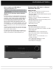
AVR 3600 OM cover.
SAFETY INFORMATION IMPORTANT SAFETY INSTRUCTIONS 1. Read these instructions. 2. Keep these instructions. 3. Heed all warnings. 4. Follow all instructions. 5. Do not use this apparatus near water. 6. The A/V receiver’s cabinet may be cleaned by gently wiping with a soft cotton or microfiber cloth. Do not use water or any liquid cleaners. 7. Do not block any of the ventilation openings. Install in accordance with the manufacturer’s instructions. 8.
SAFETY INFORMATION IMPORTANT SAFETY INFORMATION Verify Line Voltage Before Use Your AVR 3600 has been designed for use with 120-volt AC current. Connection to a line voltage other than that for which it is intended can create a safety and fire hazard and may damage the unit. If you have any questions about the voltage requirements for your specific model, or about the line voltage in your area, contact your selling dealer before plugging the unit into a wall outlet.
TABLE OF CONTENTS 2 5 7 9 11 15 17 18 18 18 18 18 18 19 19 19 19 20 20 21 22 24 24 24 24 24 24 24 24 29 29 29 29 33 33 33 33 33 34 34 34 34 34 34 35 35 36 37 37 37 38 4 SAFETY INFORMATION INTRODUCTION FRONT-PANEL CONTROLS REAR -PANEL CONNECTIONS MAIN REMOTE CONTROL FUNCTIONS ZONE 2 REMOTE CONTROL FUNCTIONS INTRODUCTION TO HOME THEATER CONNECTIONS Speaker Connections Subwoofer Connecting Source Devices to the AVR Audio Connections Digital Audio Analog Audio Video Connections Digital Video Analog Video Ante
INTRODUCTION Please register your AVR 3600 at www.harmankardon.com. NOTE: You’ll need the product’s serial number. At the same time, you can choose to be notified about new products and/or special promotions. Thank you for choosing a Harman Kardon® product! For more than fifty years, the Harman Kardon® mission has been to share a passion for music and entertainment, using leading-edge technology to achieve premium performance. Harman Kardon, Inc.
INTRODUCTION Audio Inputs Ease of Use • AM/FM/SIRIUS * tuner • Analog Audio 1 through 5 • Front-panel Analog Audio • 6-/8-Channel Analog Audio • EzSet/EQ™ automated setup (microphone supplied) • Full-color user interface and setup menu, generated in high-definition video • Two-line dot-matrix front-panel display • Color-coded connections • Programmable, learning seven-device main remote control (includes AVR control over The Bridge III) • Source input renaming • Lip Sync Delay (up to 180msec) • USB port
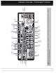
Setup Info Settings Resolution Audio Effects Video Modes Surround Modes Back/Exit / Navigation Analog Audio Front Inputs Video Front Input Volume Headphone Jack/EzSet/EQ Source List Microphone Digital Input USB Audio Inputs Remote (Optical and IR Sensor Port Coaxial Front) OK / Navigation Message Display NOTE: To make it easier to follow the instructions throughout the manual that refer to this illustration, a copy of this page may be downloaded from the Product Support section at www.
FRONT- PANEL CONTROLS Power Indicator: This LED has three possible modes: • Main Power Off: When the AVR is unplugged or the rearpanel Main Power Switch is off, this LED is off. • Standby: Amber indicates that the AVR is ready to be turned on. • On: When the AVR is turned on, this LED turns white. NOTE: If the PROTECT message ever appears, turn off the AVR and unplug it. Check all speaker wires for a possible short.
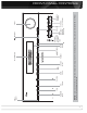
Preamp Outputs Subwoofer Output A-BUS IR Output Front Speaker Outputs Video 2 Output Video 1, 2 & 3 Inputs Surround Back/ Zone 2 Speaker Outputs Remote IR Output Remote IR Input Surround Speaker Outputs HDMI 1-4 Inputs The Bridge III Zone 2 IR Input Video Monitor Output Component Video Monitor Output Optical 1-3 Coaxial Digital Digital Audio Audio Inputs Output Center Main Switched AC Speaker Power Accessory Outputs Switch Outlet SIRIUS Tuner HDMI Monitor Output Fan Vents AC Power Input 6
REAR - PANEL CONNECTIONS Main Power Switch: This mechanical switch turns the Analog 1 – 5 Inputs: Connect the left and right analog power supply on or off. It is usually left on, and cannot be turned on or off using the remote control. audio outputs of a source device to any of these inputs. These inputs may be paired with any video inputs.
REAR - PANEL CONNECTIONS Component Video Monitor Outputs: If you are using one of the Component Video Inputs and your television or video display is component-video-capable (but does not have an HDMI input), connect these jacks to the video display. NOTES: • Due to copy-protection restrictions, there is no output at the Component Video Monitor Outputs for copy-protected sources. • Composite video signals are upscaled to as high as 1080i and available at these outputs.
MAIN REMOTE CONTROL FUNCTIONS IR Transmitter Lens AVR Power Off AVR Power On Device Power On Device Power Off Source Selectors Video Modes Surround Modes Audio Effects Alphanumeric Keys Activity Last Back/Exit Menu Navigation OK Disc Menu Light Soft keys Channel Volume Mute Transport Controls Record Info Settings Setup Zone Selector Learn SETUP INFO SLEEP Sleep Settings LEARN NOTE: To make it easier to follow the instructions throughout the manual that refer to this illustration, a copy of
MAIN REMOTE CONTROL FUNCTIONS The AVR 3600 remote is capable of controlling 8 devices, including the AVR itself and an iPod docked in the included The Bridge III. During the installation process, you may program the codes for each of your source components into the remote. To operate a component, press its Selector button to change the device mode.
MAIN REMOTE CONTROL FUNCTIONS Soft keys: These buttons are used with some source devices. See Table A13 in the appendix for details. They are also used with a Teletext-capable television if your broadcast, cable or satellite provider offers Teletext service. Channel/Page Control: When the tuner has been selected, this control selects a preset radio station. While operating a cable, satellite or HDTV set-top box or a television, press these buttons to change channels.
ZONE 2 REMOTE CONTROL FUNCTIONS IR Transmitter Power Off OFF Mute Not Used Source Selectors Info AVR Back/Exit Menu Back/Exit Sleep Settings Info Settings Menu Navigation OK Volume Controls Transport Controls Zone Selector Zone Indicator ZR 60 NOTE: To make it easier to follow the instructions throughout the manual that refer to this illustration, a copy of this page may be downloaded from the Product Support section at www.harmankardon.com.
ZONE 2 REMOTE CONTROL FUNCTIONS The Zone 2 remote control is used in the remote zone of a multizone system with an IR receiver connected to the Zone 2 IR Input or an A-BUS device. It may be used to control the power, volume and mute functions or to select a source input for the remote zone, and to control a Harman Kardon source connected to one of the AVR’s Remote IR Outputs or the A-BUS IR Output.
INTRODUCTION TO HOME THEATER This introductory section will help you to familiarize yourself with some basic concepts unique to multichannel surround sound receivers, which will make setup and operation smoother. power of an explosion, adding realism and excitement to your home theater. Some people use two subwoofers, for additional power and even distribution of the sound.
CONNECTIONS There are different types of audio and video connections used to connect the receiver, the speakers, the video display, and the source devices. The Consumer Electronics Association has established the CEA® color-coding standard. See Table 1.
CONNECTIONS NOTE: Some DVD-Audio, SACD, Blu-ray Disc and HD-DVD players only output multichannel audio through their multichannel analog outputs. Make a separate analog audio connection in addition to the HDMI connection, which is still used for video and to listen to Dolby Digital, DTS or PCM materials that may be stored on the disc. The AVR 3600 converts analog video signals to the HDMI format, including its on-screen menus, upscaling to high-definition 1080p resolution.
CONNECTIONS audio jack. Do not plug a composite video cable into an analog or coaxial digital audio jack, or vice versa. Both the chrominance (color) and luminance (intensity) components of the video signal are transmitted using a single cable. See Figure 10. Composite video cable Figure 10 – Composite Video USB PORT Component video separates the video signal into three components – one luminance (“Y”) and two sub-sampled color signals (“Pb” and “Pr”) – that are transmitted using three separate cables.
SPEAKER PLACEMENT Optimally, the speakers should be placed in a circle with the listening position at its center. The speakers should be angled so that they directly face the listening position. Green SUB C Purple FR Red White FL Front Speaker Placement The center speaker is placed either on top of, below or mounted on the wall above or below the video display screen. The front left and right speakers are placed along the circle, about 30 degrees from the center speaker and angled toward the listener.
GETTING STARTED Installing the AVR 3600 and connecting it to the other system components can be complex. To simplify installation, it is suggested that you design your system before you begin connecting wires and cables. Although the rear-panel jacks allow for a variety of audio and video connections to other components, the AVR’s software organizes the connections into 6 conventional sources: Cable/SAT, DVD, TV, Game, Media Server and AUX.
GETTING STARTED 6. Decide which audio inputs to connect to each source: Assign only one unique digital audio input to each digital source. Assign analog audio inputs to analog sources, or as secondary connections for digital sources for backup, for recording or to make the source available to the multizone system. • Any source using an HDMI Input requires no additional connection for audio unless: The source doesn’t output multichannel audio through its HDMI output.
INSTALLATION You are now ready to begin installing the AVR. Before beginning to connect the various components to the receiver, turn off all devices, including the AVR 3600, and unplug their power cords. Don’t plug in any of the power cords until you have finished making all of your connections. The receiver generates heat. Select a location that leaves several inches of space on all sides. Avoid completely enclosing the receiver inside an unventilated cabinet.
INSTALLATION STEP NINE – Install a Multizone System The AVR 3600 offers several methods of distributing audio to other areas in your home. IMPORTANT SAFETY NOTE: Installing a multizone system typically requires running cables inside walls. Always comply with the appropriate safety codes when installing concealed wiring, particularly all applicable state and local building codes and the NEC (National Electrical Code). Failure to do so may present a safety hazard.
INSTALLATION Leave the Zone Selector Switch at the bottom in the Zone 1 position for normal use. If the remote seems to operate intermittently, or if pressing a button on the remote does not cause the Setup Button or one of the Source Selectors to light, check or replace the batteries. STEP TWELVE – Program Sources Into the Remote The AVR 3600 remote may be programmed to control many brands and models of DVD players, cable boxes, satellite receivers, the Harman Kardon DMC 1000 digital media center and TVs.
INSTALLATION 2. There are several ways to turn on the AVR from Standby mode. a) Press the Standby/On Switch on the front panel. b) Using the remote, press the AVR Power On Button or any of the Source Selectors. NOTES: • Any time you press one of the Source Selectors on the remote, the remote will switch device modes. To control the receiver, press the Setup Button.
INITIAL SETUP In this section, you will configure the AVR 3600 to match your actual system. A video display must be connected to one of the video monitor outputs on the receiver. USING THE ON-SCREEN MENU SYSTEM Although it’s possible to configure the AVR using only the remote and the front-panel messages, it is easier to use the full-screen menu system. The menu system is accessed by pressing the Setup Button on the remote or front panel.
INITIAL SETUP NOTE: The AVR 3600 will automatically set its master volume to – 25dB. STEP FOUR – After you select “Continue”, the screen shown in Figure 22 will appear. Select the number of speakers in your system. Select 5.1 if no surround back speakers are present, or if the surround back channels will be used for multizone operation. established by the EzSet/EQ process. Set Up Sources The Info Settings menu is used to assign the correct physical audio and video connections to each source.
INITIAL SETUP selected. If not, the AVR will select the analog audio input specified at the Audio Auto Polling line of the Info Settings menu. If you don’t want the AVR to select an analog audio input for the source, leave this setting at its default of Off. The AVR will also select the assigned video source. The only “audioonly” sources on the AVR 3600 are the Radio and The Bridge III, (video may be available; See page 37), which use special on-screen menus.
INITIAL SETUP Resolution From Source: Informational only. Indicates the resolution of the video output by the source device. HDMI Bypass: When an HDMI source signal is in use and the system includes an HDMI-capable display, the HDMI Bypass mode passes the source signal directly to the HDMI output, bypassing all video processing within the AVR, including video Output resolution adjustment.
OPERATION Now that you have installed your components and completed a basic configuration, you are ready to begin enjoying your home theater system. TURNING ON THE AVR 3600 Flip the rear-panel Main Power Switch to the “ON” position. The Power Indicator on the front panel will turn amber, indicating that the AVR is in Standby mode and is ready to be turned on. The Main Power Switch is normally left on. There are several ways to turn on the AVR 3600: a) Press the Standby/On Switch on the front panel.
OPERATION your speakers’ sensitivity and 88dB. If they have a sensitivity rating of less than 88dB SPL, decrease Calibration Offset by the difference between your speakers’ sensitivity and 88 dB. To adjust the Calibration Offset, press the Setup Button and scroll to the System Setup menu, then select it. Scroll to the Dolby Volume Calibration line, which defaults to 0dB. Use the 7/3 Buttons to adjust the setting within the range of –10dB to +10dB.
OPERATION Use the 1/5 Buttons or the Channel Control to tune a station (or channel for SIRIUS Radio), as displayed on the front panel and on screen. The AVR defaults to automatic tuning, meaning each press of the 1/5 Buttons scans through all frequencies until a station with acceptable signal strength is found. To switch to manual tuning, in which each press of the 1/5 Buttons steps through a single frequency increment (0.1MHz for FM, or 10kHz for AM), press the Menu Button.
OPERATION section, insert blank media and make sure the recorder is turned on and recording while the source is playing. NOTES: 1. Analog and digital audio signals are not converted to the other format. 2. Only PCM digital audio signals are available for recording. Proprietary formats such as Dolby Digital and DTS may not be recorded using the digital audio connections. Use the analog audio connections to make an analog recording. 3. HDMI and component video sources are not available for recording. 4.
OPERATION NOTE: The iTunes application allows you to exempt some tracks from Shuffle mode. The AVR 3600 cannot override this setting. While a selection is playing, the song title and playmode icon will appear in the front-panel Message Display. If a video monitor is connected to the AVR 3600 and the system is not in iPod Manual Mode, the Now Playing screen will appear and display the play mode icon, song title, artist and album. A graphic bar indicates the current play position within the track.
OPERATION Virtual Surround: When only two main speakers are present in the system, Harman Virtual Surround may be used to create an enhanced soundfield that virtualizes the missing speakers. Select between Wide and Reference modes. Stereo: When 2-channel playback is desired, select the number of speakers used for playback: • 2 CH STEREO uses only two speakers. As described on page 40, you may select Analog Bypass mode for a pure analog signal when analog audio inputs are in use.
ADVANCED FUNCTIONS Much of the AVR 3600’s performance is handled automatically, with little intervention required on your part. The AVR 3600 is capable of being customized to suit your system and your tastes. In this section, some of the more advanced adjustments available are described. AUDIO PROCESSING AND SURROUND SOUND Audio signals output by sources are encoded in a variety of formats that can affect not only the quality of the sound but the number of speaker channels and the surround mode.
ADVANCED FUNCTIONS The first number indicates the number of front channels in the signal: “1” represents a monophonic recording, usually an older program that has been digitally remastered or, more rarely, a modern program for which the director has chosen a special effect. “2” indicates the presence of the left and right channels, but no center channel. “3” indicates that all three front channels (left, right and center) are present.
ADVANCED FUNCTIONS are unable to run EzSet/EQ calibration, or if you wish to make further adjustments, use the Manual Speaker Setup on-screen menus. Before beginning, place your loudspeakers as explained in the Speaker Placement section, and connect them to the AVR. Consult the owner’s guide for the speakers or the manufacturer’s Web site for the frequency range specification.
ADVANCED FUNCTIONS The main room will be configured automatically for up to 5.1 channels. See the Multizone Operation section for more information. NOTE: When the Surround Back speakers are set to “Zone 2”, they will not be configured during the EzSet/EQ process. To use the speakers in the main listening area, configure them as “On”, and run the EzSet/EQ process for a 7.1-channel system. If the speakers will only be used during multizone operation, configure them manually, as explained below.
ADVANCED FUNCTIONS STEP FOUR – Setting Channel Output Levels Manually For a conventional 2-channel receiver, the balance control affects the stereo imaging by adjusting the relative loudness of the left and right channels. With up to seven main channels, plus a subwoofer, imaging becomes both more critical and more complex. The goal is to ensure that each channel is heard at the listening position with equal loudness. EzSet/EQ calibration can handle this critical task for you, simply and automatically.
ADVANCED FUNCTIONS jagged edges and moiré patterns seen with less advanced processing. The “Torino” video processing chip generates on-screen graphics in high definition, and blends it with the incoming video, so that you can continue to watch a program while using system menus. The video processor automatically provides the best picture based on the capabilities of your video display and the incoming source video.
ADVANCED FUNCTIONS objects or the scrolling credits in a film, or if the image appears to “pixellate” into blocks, change the MPEG Noise Reduction setting from Off to Low, Medium or High. Cross Color Suppressor: Turn this setting on to remove cross color artifacts, which can occur when high-frequency luminance (brightness) signals are misinterpreted as chroma (color) signals, causing unwanted flickering, flashing colors or rainbow patterns.
ADVANCED FUNCTIONS Convergence and Edge Focus Volume: The volume is controlled separately for the remote zone. The crosshatch pattern that may surround the test screen may be used to evaluate edge focus and convergence in front- or rearprojection video displays. If you are unable to improve the picture using the available controls, contact the video display manufacturer’s authorized service representative for assistance. When you have finished making any video adjustments, press the Back/Exit Button.
ADVANCED FUNCTIONS HDMI Audio to TV: Determines whether HDMI audio signals are passed through the HDMI Output to the video display. In normal operation, leave this setting Off, as audio will be played through the AVR. To use the TV by itself, without the home theater system, turn this setting On. Mute the TV’s speakers when using the AVR for audio. Dolby Volume Calibration: This setting determines the Dolby Volume Calibration Offset, as described on page 32.
ADVANCED FUNCTIONS NOTE: Use caution when programming complicated activities. It isn’t possible to program a pause or delay before sending commands after Power On, and the component may not be ready to respond to commands immediately after powering on. If the receiver does not function correctly ofter a processor reset, contact an authorized Harman Kardon service center for assistance Authorized service centers may be located by visiting the Web site at www.harmankardon.com.
TROUBLESHOOTING GUIDE Symtom Cause Solution Unit does not function when Main Power Switch is turned on • No AC Power • Make certain AC power cord is plugged into a live outlet • Check whether outlet is switch-controlled Display lights, but no sound or picture • Intermittent input connections • Mute is on • Volume control is down • Secure all input and speaker connections • Press Mute Button • Turn up volume control No sound from any speaker; PROTECT message appears on front panel • Amplifier is in
APPENDIX Appendix – Default settings, worksheets, remote product codes Table A1 – Recommended Source Component Connections Device Type AVR 3600 Source Digital Audio Connection Analog Audio Connection Video Connections Cable TV, satellite TV, HDTV or other device that delivers television programs Cable/SAT HDMI 2 Analog 1 HDMI 2 DVD Audio/Video, SACD, Blu-ray Disc, HD-DVD player DVD HDMI 1 Analog 2 HDMI 1 Media Server, including Harman Kardon DMC 1000 Media Server HDMI 4 Analog 5 HDMI 4 TV
APPENDIX Table A3 – Speaker/Channel Setting Defaults All Digital and 2-Channel Analog Audio Inputs 6-/8-Channel Your Settings Analog Audio Inputs* Position 1 Left/Right Speakers ON ON Center Speaker ON ON Left/Right Surround Speakers ON ON Left/Right Surround Back Speakers OFF OFF Subwoofer 1 ON ON Subwoofer 2 ON ON Left/Right Speakers Crossover 100Hz Large* Center Speaker Crossover 100Hz Large* Left/Right Surround Speakers Crossover 100Hz Large* Left/Right Surround Back Speaker
APPENDIX Table A5 – Source Settings Cable/Sat DVD Media Server Radio TV Game AUX The Bridge Device Type Surround Modes Video Input The Bridge III Audio Input The Bridge III Resolution to Display Adjust Lip Sync Change Name N/A Audio Auto Polling N/A Zone 2 Audio The Bridge III Dolby Volume Table A6 – Audio Effects Settings Default Dolby Volume See Source Tone Control Off Treble 0dB Bass 0dB LFE Trim 0dB MP3 Enhancer Off Cable/Sat DVD Media Server Radio TV Game AUX The Bri
APPENDIX Table A7 – Video Modes Settings Default Video Mode Off Brightness* 50 Contrast* 50 Color* 50 Sharpness* 50 Picture Adjust Auto Fit Overscan On Noise Reduction** Low Cable/Sat DVD Media Server Radio TV Game AUX The Bridge MPEG Noise Reduction** Low Cross Color Suppressor** On Black Level** Off Deinterlacing** On Film Mode Detect** 3:2 Note: These settings are only available when the Video Mode is set to Custom.
APPENDIX Table A9 – Remote Control Codes Source Input Device Type (if changed) Product Brand and Code Number Feature Default Your Settings Front-Panel Dimmer On 100% Volume Units dB Volume Default Off Volume Default Level –25dB Unit of Measure Feet Language English HDMI Audio to TV Off Dolby Volume Calibration 0dB Transparency Medium Volume/Status Messages 3 seconds Menus 1 minute Setup and Slide-In Menus 15 minutes Screen Saver 10 minutes Software Version Check your product
APPENDIX Table A12 – Surround Modes Surround Mode Description Incoming Bitstream or Signal Dolby Digital Provides up to five separate main audio channels and a dedicated low-frequency effects (LFE) channel. • Dolby Digital 1/0/.0 or .1, 2/0/.0 or .1, 3/0/.0 or .1, 2/1/.0 or .1, 2/2/.0 or .1, 3/2/.0 or .1 • Dolby Digital EX (played as 5.1) • Dolby Digital Plus decoded and delivered via coax or optical connection Dolby Digital EX An expansion of Dolby Digital 5.
APPENDIX Table A12 – continued Surround Mode Description Incoming Bitstream or Signal Dolby Pro Logic IIx Movie This mode is similar to Dolby Pro Logic II Movie, with an added surround back channel. • Dolby Digital 2/0/.0 or .1, 2/2/.0 or .1, 3/2/.0 or .1, EX • Analog (2-channel) • Tuner • PCM (32kHz, 44.1kHz, 48kHz, 96kHz) Dolby Pro Logic IIx Music This mode is similar to Dolby Pro Logic II Music, including the availability of center width, dimension and panorama adjustments.
APPENDIX Table A12 – continued Surround Mode Description Incoming Bitstream or Signal DTS Stereo Delivers a 2-channel downmix of DTS Digital materials, or presents a matrix-encoded surround presentation. • DTS 1/0/.0 or .1, 2/0/.0 or .1, 3/0/.0 or .1, 3/1/.0 or .1, 2/2/.0 or .1, 3/2/.0 or .
APPENDIX 1 2 5 3 6 7 8 10 11 12 9 13 14 15 16 17 18 19 20 21 22 23 24 25 26 27 28 29 30 31 32 33 35 34 37 Refer to the numbered buttons in Figure 40 when using the Function List.
APPENDIX Table A13 – Remote Control Function List No.
APPENDIX Table A13 – continued No.
APPENDIX Refer to Tables A14 through A24 when programming the codes for your components into the remote.
APPENDIX Table A14 – continued Table A16 – continued TV Manufacturer/Brand Setup Code Number VCR Manufacturer/Brand Setup Code Number TATUNG TECHNICS TECHWOOD TEKNIKA TELERENT TERA THOMSON TMK TOSHIBA TOTEVISION VIDEO CONCEPTS VIDTECH WARDS YAMAHA YORK YUPITERU ZENITH ZONDA 063 181 128 045 069 156 190 128 063 132 160 128 069 123 128 045 069 122 JENSEN JVC KENWOOD LG/GOLDSTAR LLOYD LXI MAGIN MAGNAVOX MARANTZ MEMOREX MGA MITSUBISHI MULTITECH NAD NATIONAL NEC NORDMENDE OPTIMUS ORION PANASONIC PHILCO PHI
APPENDIX Table A17 – Remote Control Product Codes: AUX- CD Table A17 – continued CD Manufacturer/Brand Setup Code Number CD Manufacturer/Brand Setup Code Number ADCOM AIWA AKAI AUDIO TECHNICA AUDIOACCESS AUDIOFILE BSR CALIFORNIA AUDIO CAPETRONIC CARRERA CARVER CASIO CLARINETTE DENON EMERSON FISHER FRABA FUNAI GE GENEXXA HAITAI HARMAN KARDON HITACHI INKEL JC PENNEY JENSEN JVC KENWOOD 063 072 050 053 125 211 044 109 070 087 136 117 166 187 052 055 117 126 164 108 099 001 093 216 098 153 176 030 178 016
APPENDIX Table A19 – Remote Control Product Codes: SAT Table A20 – Remote Control Product Codes: GAME SAT Manufacturer/Brand Setup Code Number Game Manufacturer/Brand Setup Code Number ALPHASTAR ALPHASTAR DBS ALPHASTAR DSR BIRDVIEW CHANNEL MASTER CHAPARRAL CITOH DRAKE DX ANTENNA ECHOSTAR 472 450 442 425 320 315 360 313 331 395 484 392 324 303 455 463 437 366 454 410 453 317 461 453 423 373 466 487 366 457 420 418 375 407 381 412 301 458 349 442 335 339 405 459 347 327 330 302 323 381 384 MICROSOFT (X
APPENDIX Table A21 – continued CBL Manufacturer/Brand Setup Code Number SAMSUNG SCIENTIFIC ATLANTA SEAM SIGNATURE SPRUCER STARCOM STARGATE TANDY TELECAPATION TEXSCAN TFC TIMELESS TOCOM UNITED CABLE UNIVERSAL VIDEOWAY VIEWSTAR ZENITH ZENTEK 003 183 121 001 053 002 120 024 028 036 122 123 170 011 033 124 019 065 116 072 203 186 221 188 081 011 177 163 189 039 042 113 086 211 089 219 190 222 205 034 211 025 125 Table A22 – Remote Control Product Codes: AUX-MEDIA SERVER Manufacturer/Brand Setup
AVR 3600 TECHNICAL SPECIFICATIONS Audio Section Stereo Mode, Continuous Average Power (FTC) 85 Watts per channel, 20Hz–20kHz, @ <0.07% THD, both channels driven into 8 ohms Seven-Channel Surround Modes Power per Individual Channel Front L & R channels: 85 Watts per channel @ <0.07% THD, 20Hz–20kHz into 8 ohms Center channel: 85 Watts @ <0.07% THD, 20Hz–20kHz into 8 ohms Surround (L & R Side, L & R Back) channels: 85 Watts per channel @ <0.
AVR 3600 OM cover.qxd 3/10/09 4:40 PM Page 2 250 Crossways Park Drive, Woodbury, New York 11797 www.harmankardon.com © 2009 Harman International Industries, Incorporated. All rights reserved. Part No.