ENGLISH AVR 155 Audio/VideoReceiver OWNER’S MANUAL
Table of Contents 3 4 4 5 7 9 13 13 13 14 14 15 16 16 17 17 17 17 18 19 19 20 21 23 23 26 27 30 30 32 32 32 32 33 33 33 33 34 34 34 34 35 35 35 36 37 37 38 38 39 39 39 39 40 40 40 41 41 41 41 42 42 42 42 43 43 Introduction Safety Information Unpacking Front Panel Controls Rear Panel Connections Main Remote Control Functions Installation and Connections Audio Connections Video Connections HDMI Connections SCART A/V Connections Power Connections Speaker Selection Speaker Placement System Configuration First
Thank you for choosing Harman Kardon! With the purchase of a Harman Kardon AVR 155 you are about to begin many years of listening enjoyment. Designed to provide all the excitement and detail of movie soundtracks and every nuance of musical selections, the AVR is truly a multichannel receiver for the new millennium. In addition to the traditional 5.
Safety Information Important Safety Information READ THIS BEFORE OPERATING YOUR UNIT Do not install this equipment in a confined space such as a case or similar – away from direct sunlight, heat sources, vibration, dust, moisture, and/or cold. Avoid installing this unit where foreign object may fall onto this unit and/or this unit may be exposed to liquid dripping or splashing. On the top of this unit, do not place: – Burning objects (i.e.
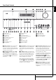
ENGLISH Front Panel Controls 1 Volume Control 2 System Power Control 3 Power Indicator 4 Headphone Jack 5 Surround Mode Group Selector 6 Speaker Select Button 7 Selector Buttons 8 Tone Mode 9 Surround Mode Selector ) Tuning Up/Down ! Tuner Band Selector @ OK Button # Preset Stations Selector $ Speaker/Channel Input Indicator % Input Source Selector ^ RDS Select Button & Delay * Digital Optical 3 Input ( Channel Select Button Ó Digital Coax 3 Input Ô Video 3 input jacks Digital Input Selector Ò Main In
Front Panel Controls 7 Selector Buttons: When you are establishing the AVR’s configuration settings, use these buttons to select from the choices available, as shown in the Main Information Display Ò. 8 Tone Mode: Pressing this button enables or disables the Balance, Bass and Treble tone controls. When the button is pressed so that the words TONE IN appear in the Main Information Display Ò, the settings of the Bass and Treble controls and of the Balance control will affect the output signals.
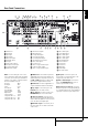
O 4 0 1 2 3 4 5 6 7 8 9 A P Q C B 7 H 5 D AM Antenna FM Antenna Tape Inputs Tape Outputs Subwoofer Output DVD Audio Inputs CD Inputs Video 1 Audio Outputs Aux input stereo minijack 6-Channel Direct Inputs Digital Audio Outputs NOTE: To assist in making the correct connections for multichannel input/output and speaker connections, all connection jacks and terminals have been color coded in conformance with the latest CEA standards as follows: Front Left: White Front Right: Red Center: Green Surround Le
Rear Panel Connections 9 6-Channel Direct Inputs: These jacks are used for connection to source devices such as DVD-Audio or SACD players with discrete analog outputs. G Switched AC Accessory Outlet: This outlet may be used to power any device that you wish to have turn on when the AVR is turned on with the System Power Control switch 2. A Digital Audio Output: Connect this jack to the matching digital input connector on a digital recorder such as a CD-R or MiniDisc recorder.
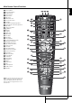
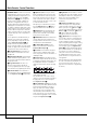
0 1 2 3 4 5 6 7 8 9 A B C D E F G H I J K L M N O P Q Power Off Button IR Transmitter Window Program Indicator Power On Button Input Selectors AVR Selector AM/FM Tuner Select 6-Channel Direct Input Test Button Sleep Button and Program Up Button Surround Mode Select and Program Down Night Mode Channel Select Button ⁄ / ¤ Buttons ‹ Button OK Button Digital Select Numeric Keys Tuner Mode Direct Button Tuning Up/Down On-Screen Display Button (OSD) Dolby Mode Select Button DTS Digital Mode Selecto
Main Remote Control Functions IMPORTANT NOTE: The AVR 155’s remote may be programmed to control up to seven devices, including the AVR. Before using the remote, it is important to remember to press the Input Selector button 45 that corresponds to the unit you wish to operate. In addition, the AVR’s remote is shipped from the factory to operate the AVR and most Harman Kardon CD or DVD players and cassette decks.
E ‹ Button: This button is used to change the menu selection or setting during some of the setup procedures for the AVR. L OSD Button: Press this button to activate the On Screen Display (OSD) system used to set up or adjust the AVR’s parameters. F OK Button: This button is used to enter settings into the AVR’s memory. It is also used in the setup procedures for delay time, speaker configuration and channel output level adjustment.
Main Remote Control Functions Memory Button: Press this button to enter a radio station into the AVR ’s preset memory. Two underline indicators will flash at the right side of the Main Information Display Ò, you then have five seconds to enter a preset memory location using the Numeric Keys H. (See page 41 for more information). Delay/Prev Ch.: Press this button to begin the process for setting the delay times used by the AVR when processing surround sound.
After unpacking the unit, and placing it on a solid surface capable of supporting its weight, you will need to make the connections to your audio and video equipment. Audio Equipment Connections We recommend that you use high-quality interconnect cables when making connections to source equipment and recorders to preserve the integrity of the signals. When making connections to audio source equipment or speakers it is always a good practice to unplug the unit from the AC wall outlet.
Installation and Connections 4. Connect the digital audio outputs of a CD, MD or DVD player, satellite receiver, cable box or HDTV converter to the appropriate Optical or Coaxial Digital Inputs RN*Ó. Remember that the DVD source defaults to the Coaxial 1 Digital Input N. All other sources default to their analog inputs, although any source may be assigned to any digital audio input on the receiver.
• If you use only normal video devices the TV monitor needs an adapter from 3 RCA plugs to Scart (fig. 3) only. If also S-Video devices are used an adapter from 2 RCA+1S-Video plugs to Scart is needed additionally (fig. 6), connected to the SCART input on your TV that is provided for S-Video. Note that only the video plugs (the "yellow" cinch plug in fig. 3 and the S-Video plug in fig. 6) must be connected to the TV Monitor Output B, and the volume on the TV must be reduced to minimum.
Installation and Connections Speaker Selection No matter which type or brand of speakers is used, the same model or brand of speaker should be used for the front-left, center and front-right speakers. This creates a seamless front soundstage and eliminates the possibility of distracting sonic disturbances that occur when a sound moves across mismatched front-channel speakers.
Once the speakers have been placed in the room and connected, the remaining steps are to program the system configuration memories. Although it is necessary to assign input/output settings and surround mode choices manually, we recommend that you take advantage of the power and precision of EzSet/EQ to automatically select and enter the settings for all other audio parameters.
System Configuration speaker settings will automatically default to “Small” at all positions with the subwoofer set to “LFE.” The default setting for the surround modes is Logic 7 Music, although Dolby Digital or DTS will automatically be selected as appropriate when a source with digital encoding is in use.
The next lines in the Input Setup menu control whether or not the bass/treble tone controls are in the signal path. The normal default is for them to be in-line, but if you wish to remove them from the circuit for “flat” response, first make certain that the fi cursor is pointing to the TONE line on the menu and press the ‹ / › Navigation Button E so that OUT is highlighted in reverse video.
System Configuration When you want to use the Night mode feature, we recommend that you select the MID setting as a starting point and change to the MAX setting later, if desired. Note that the Night mode may be adjusted directly any time that Dolby Digital surround mode is selected by pressing the Night button B. When the button is pressed, the words D-RANGE followed by the current setting (MID, MAX, OFF) will appear in the lower third of the video screen and in the Main Information Display Ò.
rival those achieved with expensive test equipment and time-consuming procedures. The end result is a system calibration profile that enables your new receiver to deliver the best possible sound, no matter what type of speakers you have or what the dimensions of your listening room are.
System Configuration • System Level: A SETTING VOLUME message will appear to indicate that the system is setting the overall volume level to the proper level as a prelude to testing the individual channels. During this test, you will see a message in the last line of the menu screen change as the volume level is adjusted. Figure 5e • Speaker Check: The system will circulate a test signal to determine which channels have a speaker connected.
Step 10: If the measurements are not successful due to a missing or malfunctioning speaker, an ERROR message and menu will appear, as shown in Figure 5g. The EzSet/EQ system is programmed to look for speaker pairs at the front left/front right, surround left/surround right and surround back left/surround back right positions.
System Configuration default setting of GLOBAL will be appropriate, as most listeners do not need to have individualized speaker settings. However, some listeners, particularly those with full-range front speakers that are used for both movies and music may prefer that different speaker settings be used when listening to music through a CD player as opposed to a movie from a DVD player, VCR or cable/satellite set top.
‹/› Navigation Buttons E to choose the appropriate setting. when the AVR is being used with a digital source that contains a dedicated Low Frequency Effects, or LFE soundtrack. This allows you to use both your main and subwoofer speakers to take advantage of the special bass created for certain movies. To select that option press the ‹/ › Buttons E on the remote so that LFE appears in the onscreen menu.
System Configuration Note: These icons are available only when making setup changes without the use of the full OSD mode. As an example, in the Figure below, all speakers are set for “large,” and a subwoofer is set. Delay Settings Due the different distances between the listening position for the front channel speakers and the surround speakers, the amount of time it takes for sound to reach your ears from the front or surround speakers is different.
The delay settings may be adjusted at any time using the remote control and while viewing an on-screen image by pressing the Delay Select Button . To change one of the individual speaker positions directly, press the Delay Select Button , followed by the ⁄/¤ Navigation Button D to select the desired position as that name appears in the on-screen display and the Lower Display Line Ò. When the name of the speaker position to be adjusted appears press the OK Button F within five seconds.
System Configuration When the CHANNEL ADJUST menu first appears, the test tone is off. Use the ⁄/¤ Navigation Button D to select any channel for adjustment using an external source, such as a test disc, from which to judge the output levels. After the fi cursor is pointing to the channel to be adjusted, press the ‹/› Navigation Button E to raise or lower the output level.
Later, it is recommended that you adjust the output levels while listening to various sources, as opposed to the test tone. See page 37 for more information on trimming the output levels to external source material. NOTE: The subwoofer output level is not adjustable using the test tone. To change the subwoofer level, follow the steps for Output Level Trim Adjustment on page 37. When all channels have an equal volume level, the adjustment is complete.
Operation Surround Mode Chart MODE FEATURES DOLBY DIGITAL Available only with digital input sources encoded with Dolby Digital data. It provides up to five separate main audio channels and a special dedicated Low Frequency Effects channel. DTS 5.1 When the speaker configuration is set for 5.1-channel operation, the DTS 5.1 mode is available when DVD, audio-only music or laserdiscs encoded with DTS data are played. DTS 5.
ENGLISH Operation Surround Mode Chart MODE FEATURES DTS Neo:6 Cinema DTS Neo:6 Music These two modes are available when any analog source is playing to create a multi-channel surround presentation from conventional Matrix-encoded and traditional Stereo sources. Select the Cinema version of Neo:6 when a program with any type of analog Matrix surround encoding is present. Select the Music version of Neo:6 for optimal processing when a nonencoded, two-channel stereo program is being played.
Operation Basic Operation Once you have completed the setup and configuration of the AVR, it is simple to operate and enjoy. The following instructions should be followed for you to maximize your enjoyment of your new receiver: Turning the AVR On or Off • When using the AVR for the first time, you must press the Main Power Main Power Switch on the rear panel ON to turn the unit on.. This places the unit in a Standby mode, as indicated by the amber color of the Power Indicator 3.
sports broadcasts, radio dramas and music CDs are also recorded in surround sound. You may view a list of these programs at the Dolby Laboratories Web site at www.dolby.com stereo, using the front left and front right speakers only (plus the subwoofer, if installed and configured), press the Stereo Button 5 until DSP SURROUND OFF appears in the Main Information Display Ò.
Operation DVDs. This does not indicate a problem with the AVR, as some players cannot pass the DTS signal through to the digital outputs. If you are in doubt as to the capability of your DVD player to handle DTS DVDs, consult the player’s owner’s manual. Please note that some DVD players are shipped with their output set for Dolby Digital only. To insure that DTS data is being sent to the AVR, please check the setup menu system on your DVD player to make certain that DTS data output is enabled.
also see the message when a satellite receiver, cable set-top or HDTV tuner is in use if the digital audio is temporarily interrupted when channels are changed or when a cable box switches from a channel with a digital data stream to a channel with analog audio only. This message is normal, and does not indicate any problem with your receiver. Rather, it tells you that the incoming data has simply been paused or is not present for a variety of possible reasons. When Dolby Digital 3/2/.1 or DTS 3/2/.
Operation For incoming DTS signals, the following modes are available: Incoming Bitstream Available Surround Modes DTS 1/0/.0, 1/0/.1, 2/0/.0, 2/0/.1, 3/0/.0, 3/0/.1, 3/1/.0 or 3/1/.1 DTS, DTS Stereo DTS 2/2/.0, 2/2/.1, 3/2/.0 or 3/2/.1 DTS, DTS Stereo DTS 96/24 DTS 96/24, DTS Stereo DTS-ES Matrix DTS, DTS Stereo DTS-ES Discrete DTS, DTS Stereo is important to note that although Dolby Digital, for example, is referred to as a “5.
Tape Recording In normal operation, the audio or video source selected for listening through the AVR is sent to the record outputs. This means that any program you are watching or listening to may be recorded simply by placing machines connected to the outputs for Tape Outputs 3 or Video 1 Outputs P 7 in the record mode. When a digital audio recorder is connected to any of the Digital Audio Outputs A, you are able to record the digital signal using a CD-R, MiniDisc or other digital recording system.
Operation Dim Function Since the AVR will often be used when movies or other video programming is viewed unde lowlight conditions, you may wish to lower the brightness of the front-panel displays and indicators so that they do not distract from the video presentation. You may dim the displays using the menu system, as shown on this page, or you may control the brightness directly from the remote.
The AVR 155 is equipped with a number of advanced features that add extra flexibility to the unit’s operation. While it is not necessary to use these features to operate the unit, they provide additional options that you may wish to use. Front-Panel-Display Fade In normal operation, the front-panel displays and indicators remain on at full brightness, although you may also dim them or turn them off as shown on page 38.
System Setup Full-OSD Time Out Adjustment The FULL OSD menu system is used to simplify the setup and adjustment of the AVR using a series of on-screen menus. The factory default setting for these menus leaves them on the screen for 20 seconds after a period of inactivity before they disappear from the screen or Time Out. This Time Out is a safety measure to prevent the menu text from burning into the CRTs in your monitor or projector, which might happen if they were left on indefinitely.
Basic Tuner Operation The AVR 155’s tuner is capable of tuning AM, FM and FM Stereo broadcast stations and receiving RDS data. Stations may be tuned manually, or they may be stored as favorite station presets and recalled from a 30 position memory. Station Selection 1. Press the AM/FM Tuner Select button 6 on the remote to select the tuner as an input.
Tuner Operation RDS Operation The AVR 155 is equipped with RDS (Radio Data System), which brings a wide range of information to FM radio. Now in use in many countries, RDS is a system for transmitting station call signs or network information, a description of station program type, text messages about the station or specifics of a musical selection, and the correct time.
The AVR 155 is equipped with a powerful remote control that will control not only the receiver’s functions, but also most popular brands of audio and video equipment, including CD players, TV sets, cable boxes, VCRs, satellite receivers and other home-theater equipment. Once the AVR’s remote is programmed with the codes for the products you own, it is possible to eliminate most other remotes and replace them with the convenience of a single universal remote control.
Programming the Remote Example: One blink, followed by a one-second pause, followed by six blinks, followed by a onesecond pause, followed by four blinks indicates that the code has been set to 164.
To program the remote for Volume PunchThrough, follow these steps: 1. Press and hold the Input Selector 4 for the unit you wish to have associated with the volume control until the red light illuminates under the Input Selector 4 and note that the Program Indicator 2 will flash amber. 2. Press the Volume Up button and note that the Program Indicator 2 will stop flashing and stay amber. 3.
Function List No.
No. 1 2 3 4 5 6 7 8 9 10 11 12 13 14 15 16 17 18 19 20 21 22 23 24 25 26 27 28 29 30 31 32 33 34 35 36 37 38 39 40 41 42 43 44 45 46 47 48 49 50 51 52 53 54 55 56 57 58 59 60 61 62 63 64 65 66 67 68 Button Name Power On Power Off Mute AVR DVD CD Tape/ HDMI 1/ HDMI 2 VID 1 (VCR) VID 2 (CBL/SAT) VID 3 (TV) AM/FM 6 Ch. Select Sleep/CH+ Test Tone T/V Volume Up Surround/CH– OSD Blank Volume Down Channel/Guide Speaker/Menu ⁄ fi OK fl ¤ Digital/Exit Delay/Prev. Ch.
Troubleshooting Guide SYMPTOM CAUSE SOLUTION Unit does not function when Main Power Switch 2 is pushed • No AC Power • Make certain AC power cord is plugged into a live outlet • Check to see if outlet is switch controlled Display lights, but no sound or picture • Intermittent input connections • Make certain that all input and speaker connections are secure • Press Mute button • Turn up volume control • Mute is on • Volume control is down The Main Information Display shows the • Amplifier is in pro
Audio Section Stereo Mode Continuous Average Power (FTC) 50 Watts per channel, 20Hz–20kHz, @ < 0.07% THD, both channels driven into 8 ohms 5 Channel Surround Modes Power Per Individual Channel Front L&R channels: 40 Watts per channel, @ < 0.07% THD, 20Hz–20kHz into 8 ohms Center channel: 40 Watts, @ < 0.07% THD, 20Hz–20kHz into 8 ohms Surround channels: 40 Watts per channel, @ < 0.
APPENDIX – SETTINGS WORKSHEET Appendix – Default settings, worksheets, remote product codes Table A1 – Source Input Setting Defaults Source DVD HDMI 1 HDMI 2 Video 1 Video 2 Video 3 AUX In/ DMP CD Tape Title Tuner 6-Channel INT.
Table A4 – Source Input Settings Source Title Video Input Audio Input Auto Poll Surround Mode Tone Mode Bass Treble DVD HDMI 1 HDMI 2 Video 1 Video 2 Video 3 AUX In/DMP CD Tape AUX In/DMP --- Tuner 6-Channel Tuner --- 6-Channel --- Tuner 6-Channel†† Table A5 – Speaker/Channel Settings Source DVD HDMI 1 HDMI 2 Video 1 Video 2 Video 3 AUX In/DMP Left/Right Speaker Size Center Speaker Size Surround Speaker Size Subwoofer Left/Right Speaker Crossover Center Speaker Crossover Surround Spe
250 Crossways Park Drive, Woodbury, New York 11797 www.harmankardon.com Harman Consumer Group, Inc.: 2, route de Tours, 72500 Château-du-Loir, France © 2008 Harman Kardon, Incorporated Part No.