MODULUS II HOME THEATER SYSTEM ® Owner’s Guide
IMPORTANT SAFETY PRECAUTIONS Read First! CAUTION RISK OF ELECTRIC SHOCK DO NOT OPEN CAUTION: To reduce the risk of electric shock, do not remove cover (or back). No user-serviceable parts inside. Refer servicing to qualified service personnel. CAUTION: To prevent electric shock, do not use this (polarized) plug with an extension cord, receptacle or other outlet unless the blades can be fully inserted to prevent blade exposure.
MODULUS® II HOME THEATER SYSTEM OWNER’S GUIDE Table of Contents ii Important Safety Precautions iv Introduction iv Technology iv Ceramic Metal Matrix Diaphragms (CMMD™) iv Room-Friendly Acoustical Design 1 Unpacking the System 2 Planning Your System 2 Placement 5 Center and Satellite Speaker Connections 6 Subwoofer Controls 7 Subwoofer Connections 8 Operation 9 Room Adaptive Bass Optimization System™ (R.A.B.O.S.™) 10 Contents of the R.A.B.O.S.Test CD 10 R.A.B.O.S.
INTRODUCTION The Infinity Modulus II Home Theater System is a compact, efficient, universal satellite, center channel and subwoofer system that is ideal for reproducing multichannel audio and home theater sound. With their versatile design, the satellite speakers can be placed virtually anywhere on shelves or stands, or mounted on a wall using the supplied base.The center channel can easily be placed on top of, or on a shelf below, the television.
Unpacking the System Carefully unpack the system. If you suspect damage from transit, report it immediately to your dealer and/or delivery service. Keep the shipping carton and packing materials for future use. Open the package and verify the following contents: • (4) Modulus II Wall-Mount Brackets (Attached to Base of Satellites) • (1) Modulus II Powered Subwoofer • (1) Wall-Mount Bracket With Bubble Level for Use as Mounting Template.
PLANNING YOUR SYSTEM PLACEMENT Before deciding where to best place your speakers, survey your room and study Figures 1 and 2. NOTE:The satellite speakers can be placed directly on a shelf, or mounted on a wall using the built-in base/bracket. Subwoofer Left Front Channel Right Front Channel Center Channel Front Left and Right Channels For front left and right channels, place one satellite to the left and another to the right of the television, as shown in Figures 1 and 2.
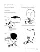
INSTALLING THE SATELLITES For Shelf Placement 1. Remove the Modulus II satellites from the box. Remove rubber cover from the base and pull out Allen wrench. 3. Run speaker wires in through the rear of the base and up through the speaker wire holes on the left and right sides of the cup restraint (see page 5, Figure 10 for wire connections). 2. Use the Allen wrench to loosen the adjustment screw (as necessary) to allow the mounting ball on the speaker to turn freely in the cup restraint.
For Wall-Mounting Note: The customer is responsible for the correct selection and use of mounting hardware (available through hardware stores) that will ensure the proper and safe wall-mounting of the speakers. 1. Remove the Modulus II from its box. Remove rubber cover from base and pull out Allen wrench. Use Allen wrench to remove mounting plate screw and remove mounting plate from base. 3. Run speaker wires through base as shown below.
CENTER AND SATELLITE SPEAKER CONNECTIONS Turn Off All Power Center Channel After placing the speakers, you are ready to connect your system. First, turn off all audio-system power. Use high-quality speaker wire to make your connections. Use at least #16-gauge speaker wire with polarity coding.The side of the wire with a ridge or other coding is usually considered positive polarity (i.e., + ).
SUBWOOFER CONTROLS Rear Panel ¡ R.A.B.O.S. On/Off Switch ™ Center-Frequency Adjustment £ Bandwidth Adjustment R.A.B.O.S. R.A.B.O.S.™ Controls Freq. ™ ¡ ON ∞ 180° Width Level £ OFF PHASE 0° ¢ R.A.B.O.S. Level Room Adaptive Bass Optimization System (R.A.B.O.S.) Controls (See p. 9 for complete R.A.B.O.S. instructions.
SUBWOOFER CONNECTIONS If you have a Dolby* Digital or DTS® receiver/processor with a low-frequency-effects (LFE) output: If your receiver/processor has subwoofer outputs for the left and right channels: RECEIVER/PROCESSOR SUBWOOFER OR LFE OUTPUT R.A.B.O.S. R.A.B.O.S.™ Controls Freq. ™ ¡ ON ∞ 180° Width £ OFF R.A.B.O.S. PHASE 0° R.A.B.O.S.™ Controls Freq.
OPERATION Surround Modes When using the Modulus II system in a Dolby Pro Logic* home theater system, make sure the receiver’s center channel mode is set to “Normal.” When using the Modulus II system in a Dolby Digital or DTS home theater system, make sure the receiver’s speaker modes are set to “Small.” Some Dolby Digital-equipped receivers/processors offer different setup options for each source or surround mode: e.g., CD-stereo, videotape, Dolby, Pro Logic.
ROOM ADAPTIVE BASS OPTIMIZATION SYSTEM Infinity R.A.B.O.S. is a simple-to-use, yet sophisticated, lowfrequency calibration system. It is designed to work in conjunction with the Infinity Modulus II self-amplified subwoofer.The Modulus II subwoofer contains a parametric equalizer that you will adjust as indicated by the R.A.B.O.S. test results. Following these instructions, you will optimize the Modulus II subwoofer’s response characteristics to complement its environment.
Power is switched on or off by pressing the button directly below the bar-graph window. When the unit is on, one or more LEDs will always be illuminated.The function of the LEDs is described in the following section. RSLM bar-graph indications Contents of the R.A.B.O.S.
Initial System-Level Setting The following steps will set the playback level of the system to the correct level for all tests that follow. Turn the system volume to minimum. Cue the R.A.B.O.S.Test CD to Track 2 and press Pause II.This track will produce band-limited pink noise in both the left and right channels. Press Play ›. As Track 3 plays, watch the RSLM carefully. Watch for peak readings.The peak reading may be no more than a brief flash.
Each of the following tracks produces a low-frequency test tone. The range of these tests is from 100Hz down to 20Hz.The frequency of each test is announced before it begins.The first test is the highest frequency (100Hz); therefore, you will be marking the template from right to left. Each frequency point is listed across the bottom of the Measurement Template (this is called the X-axis). See Figure 16 on the previous page.
R.A.B.O.S. Online Effect of adjustable width Now that you have obtained the data necessary to make final adjustments, a few more calculations are required to determine the ideal position of the three bass optimization controls. These calculations are covered in detail, and are available for your reference in the remaining pages of this owner’s guide. It is recommended that you read through to get a better understanding of the functions and benefits of R.A.B.O.S.
Using the Width Selector Placement of the Bandwidth Selector Read the following instructions carefully.The example presented may not look like the graph you just created. Focus on the concepts and techniques presented. Specific cases will be discussed later. Width Selector FIGURE 23 FIGURE 22 You will use the Measurement Template just completed and the Width Selector to determine the correct width setting.The Width Selector graphically depicts a single resonant peak.
The pointer on the slider will indicate the correct width setting. Enter this number in the Width field of the Measurement Template. In our example, the width is 12.5%. Example 1. Single Dominant Peak: Single dominant peak It is not realistic to expect a perfect fit. Acoustic measurements encompass the behavior of not only the speakers but of the room and its contents as well. Reflected energy, standing waves and ambient noise all add their part.
Example 2. Two Response Peaks: Example 3. Peak Adjacent to a Dip: Two response peaks Dip above or below peak FIGURE 26 Characterized by two response peaks, approximately equal in amplitude and width.This requires that you make a choice between the two peaks. In situations like this, the higher frequency peak will always be more audible and objectionable. Response peaks below 45Hz, unless extreme, can actually be beneficial toward achieving visceral impact.
1. Select a new test position: Cue the test track corresponding to the center frequency of the dip. In the first example in Figure 25, you would play Track 13 (56Hz). Press Play › .You will see a reading very close to what you had before. Now, slowly move the RSLM around the area, if possible remaining within about a foot of the original test point. As you move the RSLM, watch the bar graph.You will observe large level fluctuations.
1. Select a new test position: Cue the test track corresponding to the center frequency of the dip. In the example in Figure 29 you would play Tracks 14 (52Hz) and 18 (40Hz). Press Play ›. You will see a reading very close to what you had before. Now, slowly move the RSLM around the area, if possible remaining within about a foot of the original test point. As you move the RSLM, watch the bar graph.You will observe large level fluctuations.
Adjust the controls as indicated by the Measurement Template. Each value shown in the table is represented by detents in the R.A.B.O.S. controls. Simply count the number of detents necessary, indicated by the results of your R.A.B.O.S.Test. After performing these adjustments, you may skip forward to the “Final System Balance” section. It is recommended that you perform a second measurement to confirm that the settings are correct.
SPECIFICATIONS Modulus II Home Theater System Satellite Center Channel Frequency Range: 100Hz – 20,000Hz (±3dB) 80Hz – 20,000Hz (±3dB) Recommended Amplifier Power Range: 15 – 125 watts 15 – 125 watts Sensitivity: 86dB 88dB Nominal Impedance: 8Ω 8Ω Crossover Frequency: 2500Hz, 12dB/Octave 2500Hz, 12dB/Octave Midrange Driver(s): 4" CMMD,™ magnetically shielded Dual 4" CMMD,™ magnetically shielded High-Frequency Driver: 3/4" CMMD, magnetically shielded 3/4" CMMD, magnetically shielded Di
Frequency Hz dB Width % Frequency Hz dB Width % MODULUS II HOME THEATER SYSTEM 21
22 Frequency Hz dB Width % Frequency Hz dB Width % MODULUS II HOME THEATER SYSTEM
NOTES: MODULUS II HOME THEATER SYSTEM 23
© 2003 Harman International Industries, Incorporated Infinity Systems, 250 Crossways Park Drive, Woodbury, NY 11797 USA 800.553.3332 (USA only) www.infinitysystems.com * Trademarks of Dolby Laboratories. DTS is a registered trademark of Digital Theater Systems, Inc. Infinity and Modulus are registered trademarks, and CMMD (patent nos. 6,327,372 and 6,404,897) is a trademark, of Harman International Industries, Incorporated. Part No.