AVR254om.
AVR254om.qxd 3/28/08 12:45 PM Page 2 SAFETY INFORMATION Important Safety Instructions 1. 2. 3. 4. 5. 6. Read these instructions. Keep these instructions. Heed all warnings. Follow all instructions. Do not use this apparatus near water. The A/V receiver’s cabinet may be cleaned by gently wiping with a soft cotton or microfiber cloth. Do not use water or any liquid cleaners. 7. Do not block any of the ventilation openings. Install in accordance with the manufacturer’s instructions. 8.
AVR254om.qxd 3/28/08 12:45 PM Page 3 SAFETY INFORMATION Important Safety Information Verify Line Voltage Before Use Your AVR 254 has been designed for use with 120-volt AC current. Connection to a line voltage other than that for which it is intended can create a safety and fire hazard and may damage the unit. If you have any questions about the voltage requirements for your specific model, or about the line voltage in your area, contact your selling dealer before plugging the unit into a wall outlet.
AVR254om.
AVR254om.
AVR254om.qxd 3/28/08 12:45 PM Page 6 INTRODUCTION Please register your AVR 254 on our Web site at www.harmankardon.com. Note: You’ll need the product’s serial number. At the same time, you can choose to be notified about our new products and/or special promotions. WWW.HARMANKARDON.COM Thank you for choosing a Harman Kardon® product! For more than fifty years, our mission has been to share our passion for music and entertainment, using leading-edge technology to achieve premium performance.
AVR254om.
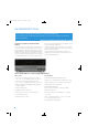
AVR254om.qxd 3/28/08 12:45 PM Page 8 FRONT-PANEL CONTROLS Main Power Switch: This mechanical switch turns the power supply on or off. It is usually left pressed in (On position), and cannot be turned on using the remote control. Standby/On Switch: This electrical switch turns the receiver on for playback, or leaves it in Standby mode for quick turn-on using this switch or the remote control.
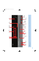
Main Power Switch Audio Effects Surround Modes Source List OK / Navigation / Navigation Digital Audio Inputs (Optical 3 and Coaxial 3) Remote IR Sensor Back/ Exit Headphone Jack/EzSet/EQ Microphone Input Speaker/Channel Input Indicators Video 4 Analog Audio Inputs Video 4 Video Inputs Volume NOTE: To make it easier to follow the instructions throughout the manual that refer to this illustration, a copy of this page may be downloaded from the Product Support section at www.harmankardon.com.
AVR254om.qxd 3/28/08 12:45 PM Page 10 FRONT-PANEL CONNECTIONS Audio Effects: Press this button to directly access the Audio Effects submenu, which allows adjustment of the tone and other controls. See the Initial Setup section for more information. Video Modes: Press this button for direct access to the Video Modes submenu, which contains settings that may be used to improve the picture if necessary after you have adjusted the picture settings using the video display or TV.
AVR254om.qxd 3/28/08 12:45 PM Page 11 REAR-PANEL CONNECTIONS AM and FM Antenna Terminals: Connect the included AM and FM antennas to their respective terminals for radio reception. XM Antenna Jack: Plug in an XM Connect and Play or Mini Tuner antenna module here. The XM antenna module is purchased separately, and should specify that it is for home use with an XM Ready® product. You will need to subscribe to the XM service, which is available separately, and activate the service for your antenna module.
AVR254om.qxd 3/28/08 12:45 PM Page 12 REAR-PANEL CONNECTIONS Analog 2 and 4 Outputs: Connect either of these analog audio outputs to the analog audio inputs of a recording device. A signal is available at these outputs whenever an analog audio source is playing. However, the AVR 254 does not convert digital audio sources to analog for recording. Coaxial 1/2 and Optical 1/2 Digital Audio Inputs: If a RS-232 Mode: Leave this switch popped out in the Operate position unless the AVR 254 is being upgraded.
Zone 2 IR Input Preamp Outputs Subwoofer Output Remote IR Output Analog 4 Outputs Coaxial Digital Audio Output XM Antenna Coaxial 1 and 2 Digital Audio Optical 1 and 2 Digital Audio RS-232 Reset AC Power Cord RS-232 Serial Port RS-232 Mode Component Video Monitor Outputs Component 1 and 2 Switched AC Accessory Outlet HDMI Monitor Output Stereo Jack Surround Center Speaker Speaker Outputs Outputs 6-/8Channel Inputs Surround Back/Zone 2 Speaker Outputs Front Speaker Outputs Video Monitor
AVR254om.qxd 3/28/08 12:45 PM Page 14 REMOTE CONTROL FUNCTIONS The AVR 254 remote is capable of controlling 7 devices, including the AVR itself. During the installation process, you may program the codes for each of your source components into the remote. Each time you wish to use the codes for any component, first press its Selector button. This changes the button functions to the appropriate codes.
AVR254om.
AVR254om.qxd 3/28/08 12:45 PM Page 16 REMOTE CONTROL FUNCTIONS Volume Control: Press this button to raise or lower the volume. Zone Selector: Use this switch to select whether AVR commands Navigation (⁄/ ¤/ ‹ / › ) and OK Buttons: These buttons are will affect the main listening area (Zone 1) or the remote zone of a multizone system (Zone 2). For normal operation, leave the switch in the Zone 1 position. used to make selections within the menu system.
AVR254om.qxd 3/28/08 12:45 PM Page 17 INTRODUCTION TO HOME THEATER The AVR 254 may be the first multichannel surround sound receiver you have owned. Although it has more connections and features than 2-channel receivers, many of the principles are similar and the new concepts are easy to understand. This introductory section will help you to familiarize yourself with the basic concepts, which will make setup and operation smoother.
AVR254om.qxd 3/28/08 12:45 PM Page 18 CONNECTIONS There are different types of audio and video connections used to connect the receiver to the speakers and video display, and to connect the source devices to the receiver. To make it easier to keep them all straight, the Consumer Electronics Association (CEA®) has established a color-coding standard. See Table 1. Table 1 – Connection Color Guide Bare wire cables are installed as follows (see Figure 2): 1.
AVR254om.qxd 3/28/08 12:45 PM Page 19 CONNECTIONS Audio Connections There are two formats for audio connections: digital and analog. Digital audio signals are required for listening to sources encoded with digital surround modes, such as Dolby Digital and DTS, or for non-compressed PCM digital audio. There are three types of digital audio connections: HDMI, coaxial and optical. Any type of digital audio connection may be used for each source device, but never more than one for the same source.
AVR254om.qxd 3/28/08 12:45 PM Page 20 CONNECTIONS required for DVD-Audio players compliant with HDMI version 1.1 or better, or HD-DVD and Blu-ray Disc players that decode the digital audio internally and output linear PCM signals in digital format. Consult the owner’s guide for your disc player for more information.
AVR254om.qxd 3/28/08 12:45 PM Page 21 CONNECTIONS Figure 14 – AM Antenna To enjoy XM satellite radio, purchase an XM antenna module designed for use with XM Ready devices and a subscription to the XM service. We recommend the XM Mini Tuner and Home Dock Bundle, available at www.xmradio.com. The older Connect and Play module is also compatible with the AVR 254, but it may no longer be available in your area.
AVR254om.qxd 3/28/08 12:45 PM Page 22 SPEAKER PLACEMENT Before you begin to connect cables, it is important to place your speakers in their correct locations in the room. Placement of Surround Speakers in a 5.1-Channel System Optimally, the speakers should be placed in a circle with the listening position at its center. The distance from the listening position to the video display forms the radius of the circle.
AVR254om.qxd 3/28/08 12:45 PM Page 23 SPEAKER PLACEMENT Subwoofer Placement The subwoofer’s location is less critical, since low-frequency sounds are omnidirectional. Placing the subwoofer close to a wall or in a corner will reinforce the low frequencies, and may create a “boomy” sound. Experiment by placing the subwoofer where the listener normally sits and then walk around the room until the low frequencies sound best. Place the subwoofer in that spot.
AVR254om.qxd 3/28/08 12:45 PM Page 24 INSTALLATION You are now ready to connect the various components to the receiver. Before beginning, turn off all components, including the AVR 254, and unplug their power cords. Don’t plug in any of the power cords until you have finished making all of your connections. Remember that the receiver generates heat while it is on. Select a location that leaves several inches of space on all sides of the receiver.
AVR254om.qxd 3/28/08 12:45 PM Page 25 INSTALLATION HDMI Connections • Choose the HDMI connection if it’s available on your source device and your TV. A HDMI connection carries both digital audio and video, enabling a single-cable connection from the source device to the AVR. Except as noted below, no other audio or video connections are required.
AVR254om.qxd 3/28/08 12:45 PM Page 26 INSTALLATION • Connect the DVD player’s digital audio output to one of the Coaxial or Optical inputs on the AVR. If the player is capable of playing multichannel discs, including DVD-Audio, SACD, Blu-ray Disc and HD-DVD, make the following additional connection (see Figure 23): AVR 254 • Connect the DVD player’s 6-/8-channel analog audio outputs to the 6-/8-Channel Analog Audio Inputs on the AVR.
AVR254om.qxd 3/28/08 12:45 PM Page 27 INSTALLATION AVR 254 AVR 254 Figure 26 – Connecting a Composite or S-Video Recorder Figure 27 – Connecting a Composite- or S-Video-Equipped Set-Top Box • To make two-channel digital audio recordings, connect the recorder’s digital audio output to one of the Optical or Coaxial Inputs, and connect the AVR’s Coaxial Digital Audio Output to the recorder’s coaxial input.
AVR254om.qxd 3/28/08 12:46 PM Page 28 INSTALLATION To make analog audio recordings, connect the recorder’s left and right analog audio outputs to the Analog 2 Audio Inputs on the AVR, and the recorder’s analog audio inputs to the AVR’s Analog 2 Audio Outputs. No video connection is required, although the AVR will display any signal at the video input assigned to the same source as the Analog 2 Audio Inputs. See Figure 29.
AVR254om.qxd 3/28/08 12:46 PM Page 29 INSTALLATION Step Seven – Insert Batteries in Remote The AVR 254 remote control uses four AAA batteries, which are included. To remove the battery cover located on the back of the remote, squeeze the tab and lift the cover. AVR 254 Insert the batteries, as shown in Figure 36, making sure to observe the correct polarity.
AVR254om.qxd 3/28/08 12:46 PM Page 30 INSTALLATION from the appendix table corresponding to the device and program it into the AUX Source Selector. Similarly, the CBL/SAT Source Selector is used for either a cable or satellite television set-top box. The first digit of the product code indicates the device type. 2. Turn on your source device. 3. This step places the remote in program mode. Refer to Figure 37. Press and hold the Source Selector. The button will turn red, then go dark.
AVR254om.qxd 3/28/08 12:46 PM Page 31 INSTALLATION To control more than one source device using the Remote IR Output, connect all sources in “daisy chain” fashion, with the AVR’s Remote IR Output connected to the first device’s Remote IR Input, the second device’s Remote IR Output connected to the next device’s Remote IR Input, and so forth. AVR 254 Step Ten – Install a Multizone System (Optional) The AVR 254 offers several methods of distributing music to other listening areas in your home.
AVR254om.qxd 3/28/08 12:46 PM Page 32 INSTALLATION Figure 42 – AVR Power On and Source Selectors NOTES: • Any time you press one of the Source Selectors on the remote (i.e., Cable/Sat, DVD, Media Server, Radio, TV, Game or AUX), the remote will switch modes to transmit the codes programmed to operate that device. To control the receiver, press the AVR Settings Button to return the remote to AVR mode.
AVR254om.qxd 3/28/08 12:46 PM Page 33 INITIAL SETUP Before you begin enjoying your new receiver, a few adjustments should be made to configure the AVR 254 to match your actual system. The current menu, setting line or setting will appear in the Message Display as well as on screen. Make sure that you have connected a video display to one of the video monitor outputs on the receiver.
AVR254om.qxd 3/28/08 12:46 PM Page 34 INITIAL SETUP Figure 45 – Plug EzSet/EQ microphone into receiver. Step Three – Make sure that the AVR 254 and the video display are turned on. Press the AVR Settings Button to display the Main Menu. See Figure 43. Use the ¤ Button to highlight the Speaker Setup line, and then press the OK Button. See Figure 46.
AVR254om.qxd 3/28/08 12:46 PM Page 35 INITIAL SETUP Step Five – During the next portion of the test, the EzSet/EQ procedure equalizes the AVR 254’s audio circuitry to compensate for the specific room characteristics and the performance capabilities of each individual speaker. To do this successfully, the EzSet/EQ microphone must be placed about two feet from each speaker in the direction toward the listening position. Wait until the on-screen instructions prompt you before moving the microphone.
AVR254om.qxd 3/28/08 12:46 PM Page 36 INITIAL SETUP Audio Input from source: Select this line to assign the correct analog or digital audio input to the source. Refer to Table A5 in the appendix, where you noted the physical audio input the source is connected to, and select the input here. If both analog and digital audio connections were made, select the digital input here, and select the analog input at the Audio Auto Polling line below.
AVR254om.qxd 3/28/08 12:46 PM Page 37 INITIAL SETUP Europe and elsewhere. The AVR 254 is capable of detecting PAL video sources and converting them to the NTSC format for display on American televisions. Adjust Lip Sync: Use this adjustment to resynchronize the audio and video signals from a source to eliminate a “lip sync” problem. Lip sync issues can occur when the video portion of a signal undergoes additional processing in either the source or the video display that desynchronizes it from the audio.
AVR254om.qxd 3/28/08 12:46 PM Page 38 OPERATION Now that you have installed your system components and completed a basic configuration of your receiver, you are ready to begin enjoying your home theater system. Turning On the AVR 254 Gently press the Master Power Switch until the word OFF is no longer visible. The Power Indicator above the two power switches should light up in amber. This indicates that the AVR is in Standby mode and is ready to be turned on.
AVR254om.qxd 3/28/08 12:46 PM Page 39 OPERATION The DOLBY H:BYPASS message indicates that Dolby Headphone surround processing is in the default bypass mode, which delivers a conventional 2-channel signal to the headphones. Additional tips for systems using HDMI: • Turn off all devices (including the TV, AVR and any source components). • Unplug the HDMI cables starting with the cable between the TV and AVR, and continuing with the cables between the AVR and each source device.
AVR254om.qxd 3/28/08 12:46 PM Page 40 OPERATION To tune a preset station, press the ‹ / › Buttons or the Channel Control, or press the Menu Button to view the list of programmed presets and scroll to the desired selection. Press the OK Button to tune the station. You may also enter the preset number using the Numeric Keys. For presets 10 through 30 press 0 before the preset number. For example, to enter preset 21, press 0-2-1. 3.
AVR254om.qxd 3/28/08 12:46 PM Page 41 OPERATION 2. Only PCM digital audio signals are available for recording. Proprietary formats such as Dolby Digital and DTS may not be recorded using the digital audio connections, although if the source is connected to the AVR using analog audio connections, an analog recording may be made. 3. HDMI and component video sources are not available for recording. 4. Please make certain that you are aware of any copyright restrictions on any material you record.
AVR254om.qxd 3/28/08 12:46 PM Page 42 ADVANCED FUNCTIONS Much of the AVR 254’s performance is handled automatically, with little intervention required on your part. However, the AVR 254 is a sophisticated component, and is capable of being customized to suit your particular system and your tastes. In this section we describe some of the more advanced adjustments available on the AVR 254. You may return to this section later, when you have become more familiar with your receiver.
AVR254om.qxd 3/28/08 12:46 PM Page 43 ADVANCED FUNCTIONS The second number indicates whether any surround channels are present: Each line is set to a default surround mode: “0” indicates that no surround information is present. “1” indicates that a matrixed surround signal is present. “2” indicates discrete left and right surround channels. “3” is used with DTS-ES bitstreams to represent the presence of the discrete surround back channel in addition to the side surround left and right channels.
AVR254om.qxd 3/28/08 12:46 PM Page 44 ADVANCED FUNCTIONS When in doubt, check the jacket of your DVD for more information on which surround modes are available on the disc. Usually, nonessential sections of the disc, such as trailers, extra materials or the disc menu, are only available in Dolby Digital 2.0 (2-channel) or PCM 2-channel mode.
AVR254om.qxd 3/28/08 12:46 PM Page 45 ADVANCED FUNCTIONS Manual Setup The AVR 254 is flexibly designed to be used with almost any loudspeakers available. The flexibility comes from the AVR 254’s capability to be configured to match the characteristics of your particular speakers, and to compensate for the acoustic characteristics of your room. The EzSet/EQ process automatically detects the capabilities of each speaker, and optimizes the AVR 254’s performance in your system.
AVR254om.qxd 3/28/08 12:46 PM Page 46 ADVANCED FUNCTIONS NOTE: All of the speaker setup submenus include the Exit and Back options as shown at the bottom of Figure 58. To return to a previous menu without making any changes, select Exit. To save the current settings, select the Back option. If you previously saved EzSet/EQ results in this setup position and you wish to reconfigure the speakers from scratch, select the Reset option.
AVR254om.qxd 3/28/08 12:46 PM Page 47 ADVANCED FUNCTIONS played through the front left and right speakers and the special low-frequency effects (LFE) channel information. section, and select the Unit of Measure line. Press the OK Button to change the setting from Feet to Meters. LFE: This setting plays low-frequency information contained in the left and right program channels to the front speakers, and directs only the LFE channel information to the subwoofer.
AVR254om.qxd 3/28/08 12:46 PM Page 48 ADVANCED FUNCTIONS The best method of setting the output levels is by running the EzSet/EQ process, as described in the Initial Setup section. If any finer adjustments are desired, we recommend using the menu system to make the adjustments while playing the AVR’s built-in test tone and measuring the output using an SPL meter. Less effective would be to measure the output by ear.
AVR254om.qxd 3/28/08 12:46 PM Page 49 ADVANCED FUNCTIONS • Half: Applies moderate compression. • Full: Applies the most compression. screen as sliders with values ranging from 0 to 100. The default setting for each adjustment is 50. Use the ‹ / › Buttons to change each setting’s value. When you have finished making adjustments in the Audio Effects menu, press the Audio Effects Button or the Back/Exit Button to clear the screen.
AVR254om.qxd 3/28/08 12:46 PM Page 50 ADVANCED FUNCTIONS blocks, change the MPEG Noise Reduction setting from its default of Off to the Low, Medium or High setting to improve the picture. Cross Color Suppressor: Turn this setting on to remove cross color artifacts, which can occur when high-frequency luminance (brightness) signals are misinterpreted as chroma (color) signals, which can cause unwanted flickering, flashing colors or rainbow patterns.
AVR254om.qxd 3/28/08 12:46 PM Page 51 ADVANCED FUNCTIONS complex, and require proper training and experience to avoid worsening the situation. Therefore, it is recommended that if you are unable to improve the picture using the available controls, contact the video display manufacturer’s authorized service representative for assistance. When you have finished making any video adjustments, press the Back/Exit Button to back out of the menu system.
AVR254om.qxd 3/28/08 12:46 PM Page 52 ADVANCED FUNCTIONS Volume: The volume is controlled separately for the remote zone. To operate the multizone system using the remote, slide the Zone Select Switch at the bottom of the remote to the “2” position (see Figure 70). Press a Source Selector to select a source input for the remote zone. Adjusting the volume or mute controls will only affect the volume in the remote zone. The on-screen menu functions will not be operative.
AVR254om.qxd 3/28/08 12:46 PM Page 53 ADVANCED FUNCTIONS Advanced Remote Control Functions The AVR 254 remote control not only operates the AVR 254, but it also serves as a universal remote that may be programmed to operate many other home theater components, as described in the Installation section. Each time you select one of your other components, the AVR remote switches to the control functions for that component.
AVR254om.qxd 3/28/08 12:46 PM Page 54 ADVANCED FUNCTIONS • The RS-232 Reset Button on the rear panel of the AVR 254 does not perform a system reset. DO NOT press the RS-232 Reset Button. To reset the AVR 254, place the receiver in Standby mode (press the front-panel Standby/On Switch so that the Power Indicator turns amber). Then press and hold the front-panel OK Button for at least five seconds until the RESET message appears in the display.
AVR254om.
AVR254om.
AVR254om.
AVR254om.
AVR254om.qxd 3/28/08 12:46 PM Page 59 APPENDIX Table A8 – Surround Modes Default Auto Select Logic 7 Movie or native digital format Virtual Surround Dolby Virtual Speaker Reference Stereo 7 CH Stereo Movie Logic 7 Movie Music Logic 7 Music Game Logic 7 Game Center Width* 0 Dimension* 0 Panorama* Off Cable/Sat DVD Media Server Radio TV Game AUX * Note: These settings are only available when Dolby Pro Logic II or IIx Music mode has been selected.
AVR254om.qxd 3/28/08 12:46 PM Page 60 APPENDIX Table A11 – Zone 2 Settings Source Input Device Type (if changed) Status Off Source Cable/Sat Volume -25dB Surround Back Amps Main Room Your Settings Table A12 – Surround Modes Surround Mode Description Incoming Bitstream or Signal Dolby Digital Provides up to five separate main audio channels and a dedicated low-frequency effects (LFE) channel.
AVR254om.qxd 3/28/08 12:46 PM Page 61 APPENDIX Surround Mode Description Incoming Bitstream or Signal Dolby Pro Logic II Game Variant of Dolby Pro Logic II that emphasizes use of the surround channels and subwoofer for total immersion in the video gaming experience. • Dolby Digital 2.0 or 2.1 • Analog (2-channel) • Tuner • PCM (32kHz, 44.1kHz, 48kHz, 96kHz) Dolby Pro Logic Original version of Dolby Pro Logic that steered a mono signal containing information below 7kHz to the surround channels.
AVR254om.qxd 3/28/08 12:46 PM Page 62 APPENDIX Surround Mode Description Incoming Bitstream or Signal DTS-HD DTS-HD is a new high-definition audio format that complements the high-definition video found on Blu-ray Discs and HD-DVD discs. It is transmitted using a DTS core with high-resolution extensions. Even when only DTS 5.
AVR254om.qxd 3/31/08 3:28 PM Page 63 APPENDIX Surround Mode Description Incoming Bitstream or Signal Logic 7 Game Use Logic 7 Game mode to enhance enjoyment of video game consoles. • Analog (2-channel) • Tuner • PCM (32kHz, 44.1kHz, 48kHz, 96kHz) 5-Channel Stereo Useful for parties, the left- and right-channel information is played through both the front and surround speakers on each side, while the center speaker plays a summed mono mix. • Analog (2-channel) • Tuner • PCM (32kHz, 44.
AVR254om.qxd 3/28/08 12:46 PM Page 64 APPENDIX 1 2 5 6 3 7 4 8 9 10 11 12 13 14 15 16 17 18 19 20 21 22 23 24 25 26 27 28 29 30 31 32 33 35 36 34 37 38 39 40 41 42 43 44 45 46 47 48 49 Refer to the numbered buttons in Figure 72 when using the Function List.
AVR254om.qxd 3/28/08 12:46 PM Page 65 APPENDIX Table A13 – Remote Control Function List No.
AVR254om.qxd 3/28/08 12:46 PM Page 66 APPENDIX Table A13 – continued No.
AVR254om.qxd 3/28/08 12:46 PM Page 67 APPENDIX Refer to Tables A14 through A24 when programming the codes for your components into the remote.
AVR254om.
AVR254om.
AVR254om.
AVR254om.
AVR254om.
AVR254om.
AVR254om.
AVR254om.qxd 3/31/08 3:28 PM Page 75 AVR 254 TECHNICAL SPECIFICATIONS Audio Section Stereo Mode Continuous Average Power (FTC) 65 Watts per channel, 20Hz–20kHz, @ <0.07% THD, both channels driven into 8 ohms Seven-Channel Surround Modes Power per Individual Channel Front L & R channels: 50 Watts per channel @ <0.07% THD, 20Hz–20kHz into 8 ohms Center channel: 50 Watts @ <0.07% THD, 20Hz–20kHz into 8 ohms Surround (L & R Side, L & R Back) channels: 50 Watts per channel @ <0.
AVR254om.qxd 3/28/08 12:46 PM Page 76 ® 250 Crossways Park Drive, Woodbury, New York 11797 www.harmankardon.com © 2008 Harman International Industries, Incorporated. All rights reserved. Part No.