Installation & Operating Manual The Harman Accentra-2 Pellet Stove “Ce manuel est disponible en Français sur demande” R4 SAFETY NOTICE PLEASE READ THIS ENTIRE MANUAL BEFORE YOU INSTALL AND USE YOUR NEW ROOM HEATER. FAILURE TO FOLLOW INSTRUCTIONS MAY RESULT IN PROPERTY DAMAGE, BODILY INJURY, OR EVEN DEATH. FOR USE IN THE U.S. AND CANADA. SUITABLE FOR INSTALLATION IN MOBILE HOMES IF THIS HARMAN ACCENTRA PELLET STOVE IS NOT PROPERLY INSTALLED, A HOUSEFIRE MAY RESULT.
Introduction 2 This heating appliance does not just have automatic ignition, it has total automatic temperature control. The Accentra has an input heat range from 0 to 40,000 BTU's. This patented feed system has a maximum feed rate of 5 lbs. per hour and a minumum (maintenance) feed rate of .75 lbs. per hour and then "off" if necessary. The hopper holds approximately 50 pounds of fuel. The unit has an easy to clean combustion system with an ash pan that holds ash from 1 ton of burned premium pellets.
Automatic Ignition/Operation 3 The Accentra pellet stove is more than just automatic ignition, it is also automatic temperature control. The automatic system will allow the fire size to be adjusted to match the heating needs and even put the fire out if necessary. If heat is needed after the fire is out, the Accentra will automatically re-ignite and adjust the fire size to match the heating need. The totally automatic room sensor mode is recommended because of its efficiency.
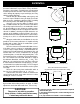
Automatic Start Up 4 Starting First Fire Ignitor Switch to"AUTO" (down position) Make sure the unit is plugged into a 120 VAC, 60 HZ electrical source. The power light should be the only light lit. See Note 7. 1" Fig. 3 1. Turn Mode Selector to "OFF". 2. Fill hopper with pellets.1 3. Clean burn pot with scraper, if necessary.5 4. If starting after an empty hopper, turn Feed Adjuster to "TEST" (for one 60 second cycle).
Manual Ignition/Operation ... ... 5 The Accentra Pellet Stove is capable of manual operation. This also allows the operator to manually control operation during an emergency (i.e. igniter failure, when using a 502H battery backup, or when using certain generators.) The unit can be switched between "AUTO" and "MANUAL" at any time during operation. NOTE: When starting the unit in the "AUTO" mode and switching to "MANUAL", the fire must be large enough to start the distribution blower.
Manual Start Up 6 Starting First Fire Ignitor Switch to"MANUAL" (up position) Fig. 8 Fig. 7 See Note 7. 1" Make sure the unit is plugged into a 120 VAC, 60 HZ electrical source. The power light should be the only light lit. 1. Turn FEED ADJUSTER to desired feed rate. No. 4 is good for most pellets.4 2. Turn the MODE SELECTOR to “OFF” and then to the desired mode. This will reset control and start the combustion motor. 3. Turn the TEMPERATURE DIAL to the desired setting. Fig. 9 4.
ESP Control Mode Selector Allows you to choose between Room Temp Mode, Stove Temp Mode, or OFF. Also allows you to vary the distribution blower speed by turning the knob to the high or low side of each mode. Dealer Diagnostic Port For dealer maintenance only. Requires special DDM monitor supplied to Harman Dealers exclusively. Di stri bu ti on Blo we r s pe ed a dj us tmen t range. L = low H = high Variable speed anywhere between L and H; although as the stove temp. goes up , so does the L and H scale.
Installation 6.25" 5"min.3 5"min 3 6.25" Fig.10 2.25" 12" Fig.11 24 1/16"* 0" 2" 2" FLOOR PROTECTOR1 6"2 Fig.12 5 28 /8"* (*Harman Cast Iron Floor Protector size) This is the minimum size Harman recommends for the alcove with a 60" ceiling. 14.75" 14.75" 24" W hen installing and operating your H arman Accentra Pellet Stove, respect basic safety standards. Read these instructions carefully before you attempt to install or operate the Accentra.
Installation 9 IMPORTANT NOTE: The Accentra unit is shipped bolted to the skid through two holes in the cast base plate. If these holes are not used to lag the unit to the floor these holes must be filled with the 3/8" x 1/ 2" hex head bolts provided. (See tag on bolt bag provided.) Skid bolt down holes/floor lag down holes Fig. 14 Adjustment of the rubber pad leveling feet The Accentra is provided with 4 rubber pad feet.
Mobile Home Installation When installing the Accentra in a mobile home several requirements must be followed: 1. The unit must be bolted to the floor. This can be done with 1/4" lag screws throught the 2 holes in the base plate shown in Fig. 16 2. The unit must also be connected for the outside air. See page 14. 3. Floor protection and clearances must be followed as shown on page 9. 4. Unit must be grounded to the metal frame of the mobile home. CAUTION: This appliance must be vented to the outside.
Low Draft Voltage Adjustment 11 Combustion Motor Speed Control Low draft only set point. The small straight screwdriver slot is plastic; therefore, the unit can be adjusted while in operation. Fig.17 These units are pre-tested at the factory with exactly 120 Volts A.C., 60 Hz. They are checked and adjusted for firebox tightness, gasket leakage, motor operation and ignitor operation. The Accentra is then factory set at a high adjustment. NOTE: Low draft adjustment may be required.
Room Sensor and Rear Shield Installation Rear Shields Room Sensor Installation 5/16" Hex Head Screws (2 on each side) 5/16" Hex Head Screws (2 on each side) Fig. 19 The room sensor is a small temperature sensor on the end of a 60" gray wire. This sensor is installed much like a standard wall thermostat. Because it is so small, it can be hidden along the trim of a doorway or even up the leg of a coffee table. There is a remote room sensor port on the rear of the unit for easy external connection.
Venting Venting IMPORTANT NOTICE Pellet Vent Pipe or PL Vent Pipe Must be used. 13 A combustion blower is used to extract the combustion gases from the firebox. This causes a negative pressure in the firebox and a positive pressure in the venting system as shown in fig. 22. The longer the vent pipe and more elbows used in the system, the greater the flow resistance. Because of these facts we recommend using as few elbows as possible and 15 feet or less of vent pipe.
Venting 14 #1 Preferred method This method provides excellent venting for normal operation and allows the stove to be installed closest to the wall. Two and a half inches from the wall is safe; however, three inches allows better access to remove the rear panel. The vertical portion of the vent should be three to five feet high. This vertical section will provide natural draft in the event of a power failure. Note: Do not place joints within wall pass-throughs. 3 ft.
Venting 15 #4 Installing into an existing chimney (US only) This method provides excellent venting for normal operation. This method also provides natural draft in the event of a power failure. If the chimney condition is questionable you may want to install a liner as in method #7. Fig.27 #5 Installing into an existing fireplace chimney (US only) This method provides excellent venting for normal operation. This method also provides natural draft in the event of a power failure.
Venting 16 #6 Installing into an existing fireplace chimney (US and Canada) This method provides excellent venting for normal operation. This method also provides natural draft in the event of a power failure. In Canada and some places in the US it is required that the vent pipe extend all the way to the top of the chimney. In this method a cap should also be installed on the chimney to keep out rain. Be sure to use approved pellet vent pipe fittings.
Venting 12" min. 17 Storm collar Flashing 3" min. 3" min. 3" min. Minimum flue vent configuration It is recommended that outside air be installed with this venting configuration to reduce smoke and creosote smell in the room in the event of power failure. No insulation or other combustible ma te ri al s are allowed within 3" of the PL ve nt pipe. (See Page 9 for corner installation clearances) Fig. 31 18" Fig.
Venting Requirements for Terminating the Venting WARNING: Venting terminals must not be recessed into a wall or siding. NOTE: Only PL vent pipe wall pass-throughs and fire stops should be used when venting through combustible materials. NOTE: Always take into consideration the effect the prevailing wind direction or other wind currents will cause with flyash and /or smoke when placing the termination. In addition, the following must be observed: A. The clearance above grade must be a minimum of 18".1 B.
Maintenance - Cleaning Glass on View Door 19 The unit should be out and cool to clean the door glass. It may not always be possible to allow the unit to cool off before cleaning. Therefore, if the unit is turned to the lowest setting about 1 hour before cleaning, it will make it possible to clean the glass with the unit in operation. Any glass cleaner with a high amonia content will work the best. Use only non-synthetic cleaning rags such as cotton or paper towels.
Maintenance - Cleaning 20 Cleaning Internal Components 1. Remove the two heat exchanger covers. See Fig. 35. These covers are made of cast iron and are held into place with a swing latch in the upper right and left corners. See Fig 36. Swing the latch upward far enough to r elease the top edge of the heat exchanger cover. Tilt the cover forwar d approximately 2" and lift it upward about 1" to release the bottom edge. The cover can now be taken completely out through the upper door opening.
Maintenance - Cleaning 21 (Cleaning Internal Components Cont'd) 2. Remove the combustion intake assembly. See Fig. 35. The combustion intake assembly is held into place with two swing latches. See Fig. 37. Swing each latch until it hangs down away from the retainer stud. Now the assembly can be taken out by tilting the right side outward first through the lower door opening. 3. The units interior is now ready to clean. Use the scraper provided to clean the heat exchanger surfaces.
Maintenance - Burn Pot 22 Burn Pot Cleaning and Maintenance 1. Scrape the top holed surface and sides of the burn pot down to auger tube.(Fig 39) It is not necessary to completely remove all material from the burn pot. The excess will be pushed out during the next use. 2. Loosen the (2) wing thumb screws on the lower front angle of the burn pot. (Fig. 40) 3. Lift off the clean-out cover (Fig.40) to open the bottom clean-out chamber. (Fig.41) DANGER Disconnect the power to the unit before removing cover.
ESP Probe The Control Board/ESP combination is responsible for all high limit safety control. There are 2 high limits, one normal operation high limit and one backup high limit. The control has an automatic diagnostic circuit that continuously monitors the ESP and Room Sensor for faults. If a fault should occur, the control sends a status alert and at the same time the unit goes down to minimum feed/minimum burn as a safety condition.
Trouble-Shooting 24 FIRE HAS GONE OUT FEEDER DOES NOT FEED 1. No pellets in hopper. 1. No pellets in hopper. 2. Draft setting is too low. 2. Firebox draft may be too low for low draft pres3. Something is restricting fuel flow. sure switch in feeder circuit to operate. Check for 4. Feed motor or draft motor has failed. closed doors, loose or missing gasket on doors 5. Power failure or blown fuse. or hopper lid, faulty pressure switch. 3.
Specifications Weight 350 lbs. Blower 150 cfm Hopper Capacity 50 lbs. Fuel Wood Pellets Outside Air Size 2 3/8 inches Fuse Rating 5 amp BTU Range 0 to 40,000 Feed Rate .75 lbs./hr. on minimum(on maintenance) 5 lbs./ hr.
Accentra Wiring Diagram 26
Cover 2-00-247217 5/16 x 18 Wing Nut 3-30-8131181 FHN 1/4-20 3-30-80252013(2) 1/2" Pillow Block 3-31-3614087 Pusher Arm 1-10-247220 A Tensioner 3/4 3-31-00075 FHN 1/4-20 3-30-80252013 5/16-18 Slab Base T-Nut 3-31-23756186(2) Auger 3-50-00365 Chain Assembly Large Sprocket 2-00-06626 3-50-08763 HX Jam 3/8-16 3-30-83371613 HCS 1/4-20 x 1 Grade 8 3-30-1252010014 Auger Retainer 2-00-04035 HCS 5/16-18 x 1-1/4 3-30-1311812513 HCS 3/8-16 x 1-1/4 3-30-1371612513 Cam Block Assembly 1-10-06628 Cam Bearing
Accentra Parts List Description Hopper Lid Gasket Ignitor Element Assembly Wiring Harness Burn Pot Weldment Right Feeder Shield w/sound proof Left Feeder Shield w/sound proof Heat Exchanger Cover (2) Arrow Scraper Flame Guide Gear Motor Thermister Probe Room Sensor Circuit Board G4220G V5.
Harman Gold Warranty 29 HARMAN GOLD WARRANTY 6 YEAR TRANSFERABLE LIMITED WARRANTY (Residential) 1 YEAR LIMITED WARRANTY (Commercial) Harman Stove Company warrants its products to be free from defects in material or workmanship, in normal use and service, for a period of 6 years from the date of sales invoice and for mechanical and electrical failures, in normal use and service, for a period of 3 years from the date of sales invoice.