Installation & Operating Manual The Harman PF 100 Pellet Pro Furnace “Ce manuel est disponible en Français sur demande” R7 SAFETY NOTICE PLEASE READ THIS ENTIRE MANUAL BEFORE YOU INSTALL AND USE YOUR NEW ROOM HEATER. FAILURE TO FOLLOW INSTRUCTIONS MAY RESULT IN PROPERTY DAMAGE, BODILY INJURY, OR EVEN DEATH. FOR USE IN THE U.S. AND CANADA. SUITABLE FOR INSTALLATION IN MOBILE HOMES IF THIS HARMAN PELLET FURNACE IS NOT PROPERLY INSTALLED, A HOUSE FIRE MAY RESULT.
PF100 Parts Fan Control Hopper Lid Latches Vent Pipe Hopper Combustion Blower cover Heat Exchanger Shaker Handle Combustion Blower 3 Speed Switch Control Cover Outer Door Latches Outer Door Viewing Glass Filter Box 2 PF100
Table of Contents Assembly 4 Venting 10 Installation 15 Operation 21 Maintenance 29 Troubleshooting 34 Feeder Parts 35 Specifications 36 Wiring Diagram 37 Parts List & Options 38 Warranty 39 Testing Label 40 Quick Reference Start-Up 41 Please read this entire manual before you install and use your new furnace. Failure to follow instructions may result in property damage, bodily injury, or even death. DO NOT INSTALL IN A MOBILE HOME.
Assembly Design The first thing that needs to be done is deciding where and how the furnace will be installed. Things that need to be taken into consideration are VENTING, SUPPLY& RETURN DUCTING, ELECTRICAL, and Condensation drainage (if A/C is installed). Don’t forget access to the furnace for service. When the return air inlet position is known the filter box and distribution blower can be installed. See pages 5, 6, 7, 8. When the furnace is set into place venting can be done. Fig. 1 Fig.
Assembly Filter Box (Cold Air Return) Top (same as bottom) Solid Side Panel Switch Blower access Panel Filter Frame Panel Blower access Panel Cover Bottom (same as top) Fig. 3 NOTE:Read and follow all of the vent pipe manufacturers’ instructions on the proper installation and support of the vent pipe. Adhere to all clearances.
Assembly Filter Frame Panel Assembling Filter Box, Cont’d 3. Place the filter frame panel inside the bottom and inside the solid panel corner. See Fig. 6 for corner detail. Make sure that the filter opening is up.See Fig. 5 Hold the filter panel to the solid panel with a Tek screw in the middle hole of the solid panel, and one in the bottom middle hole under the filter opening. Filter opening must be up NOTE: Do not put any screws into any of the top holes at this time. Fig. 5 Fig.
Assembly Assembling Filter Box, Cont’d 5. Place the top on the filter box as shown in figure 8. At this time all Tek screws can be inserted around the filter box. Note: Except for the (6) screws that attach the blower access panel in place. There should not be any screws protruding from the box on the side toward the furnace. Also DO NOT put a screw into the top center of the filter panel as a screw in this location will interfere with the filter access cover. Top 6.
Assembly Blower Assembly Install the blower mounting brackets on the blower as shown in Fig. 11. 1. Install ( 4) Tek screws on each side where shown in Fig. 11. Start with the two center screws. NOTE: There are two small holes in the discharge end of the blower that match the two center holes on the small angle of the blower bracket. The two (2) outer holes are drilled by theTek screws. Mounting Screws Fig. 11 2. Mount blower with brackets installed on the furnace as shown in Fig. 12.
Assembly Firebrick Firebrick installation-required The firebrick is shipped in the ashpan. It will need to be placed on the brick shelf as shown in Fig. 15. It can be installed with either face to the fire. Hold the brick longways and slide it down into the slot on the shelf. There is a stop at the rear of the shelf to stop the rearward travel.The brick just sits on the shelf in the upright position. Fig. 15 Baffle installation The upper heat exchanger baffle comes shipped along side the ashpan.
Venting Venting NOTE: Use only 4” diameter type “L” or “PL” venting system. Be sure to inspect and clean exhaust venting system frequently. 4” Type “L” or “PL” Vent pipe INSTALLATION IS TO BE PERFORMED BY A QUALIFIED INSTALLER. DO NOT INSTALL A FLUE DAMPER IN THE EXHAUST VENTING SYSTEM OF THIS UNIT. Fig. 18 This is the minimum venting configuration. NOTE: This would only be allowed with noncombustible walls.
Venting Configuration Graph Fig.
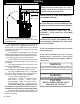
Venting Requirements for Terminating the Venting WARNING: Venting terminals must not be recessed into a wall or siding. NOTE: Only PL vent pipe wall pass-throughs and fire stops should be used when venting through combustible materials. NOTE: Always take into consideration the effect the prevailing wind direction or other wind currents will cause with flyash and /or smoke when placing the termination. In addition, the following must be observed: A. The clearance above grade must be a minimum of 18".1 B.
Venting and Clearances PF100 Skidplate Footprint 52” long Floor Protector 18” 48” wide ” Fig.21 Clearances to combustibles If installing the furnace in a room separated from the remaining living spaces, the minimum size of the room must be no smaller than 8’ x 8’. See Fig. 21. The reason for this is heat build-up and required space for service and normal operation. This is the minimum size of the room even if it is built of non-combustible material.
Venting and Installation The shaded areas are the clearances for the PL vent pipe that must be maintained at 3”. After the venting leaves the shaded area it may be installed at 2” to combustibles. (Only listed 4” pellet vent wall pass-throughs and fire stops must be used.) See Fig. 23 & 25. 181/8” 181/8” 16 16 See NOTES: on page 13 Fig. 25 Fig. 23 Chimneys taller than 20’ above the connection will require a draft test to determine if the draft is too high. Note: The High Burn Draft should not exceed .
Installation Outside Air Inlet Cover part# 1-10-09542 Fig. 27 Outside Air Pipe Knockout Fig. 28 Outside Air Inlet Pipe Outside air is optional, although it may be required by some building codes. The benefit of outside air is higher efficiency and reduced venting restrictions mainly noticed in small and very tight houses. To install outside air, use 2 3/4”" I.D.galvinized steel flex pipe, part # 2-00-08544 ( 12’ 6” length) or part # 2-00-08545 ( 25’ length).
Installation Wall Control Wiring 70 65 75 80 60 LOW FUEL Fig. 30 Fig. 31 Datacom Cable Wall Control Orange Red (+ LED ) Blue/White - Blue ( Tstat ) Orange/White - White or Black ( - LED) Blue Blue ( Tstat ) Fig. 32 The Wall Control sends and receives it’s information from the control board through a 4 wire Datacom cable. There is a 100’ length of this cable supplied with the furnace. 100’ lengths of this cable can also be ordered separately, part # 3-20-02583.
Installing Duct Installing Duct Fig. 33 The Harman PF100 may be connected to a gas or oil-fired central furnace or heat pump duct system. Prior to installation, determine whether all requirements for installation including all clearnaces can be met. The PF100 warm air supply and the cold air return must be installed in a parallel arrangement. EXAMPLE: The warm air supply duct from the PF100 is to be connected to the warm air supply of the existing furnace.
InstallingInstalling Duct/Air Duct Conditioning Recommendations for Supply Air and Return Air duct sizing. The speed or velocity of air moving through duct systems increases as the duct decreases in size with the same CFM blower. The sound of air flowing through the duct increases as the velocity increases. Therefore the largest size duct practial should be used. The velocity to sound level must be taken into consideration when connecting this furnace into an existing duct sustem.
Installation FAN/HIGH LIMIT CONTROL Installation & Set-up High limit fan control 1. The Fan Control must be placed in the discharge plenum approximately 11 inches above the discharge opening of the furnace as close to center as possible. Note: The best place is on the same side as the ash door because of ease of access. See Fig. 35. Note: Care must be taken when installing the Fan Control when an air conditioning A Coil is used.
Installation Installing Electrical Power: Fig. 37 Draft meter bolt Fig. 38 Furnace Control “Test” Low Draft Adjustment Pot Fig.39 20 PF100 To install power to the furnace first remove the cover on the circuit breaker junction box shown. Inside you will find the main terminal block.(See wiring diagram on page 36 for location of main terminal block and proper power connections). In the bottom of the box a knockout hole is provided for the incoming wire. The minimum recommended circuit is 15 Amp 120 V.
Operation Fan Control Hopper Lid Latches Vent Pipe Hopper Combustion blower cover Heat Exchanger Shaker Handle Combustion Blower 3 Speed Switch Control Cover Outer Door Latches Outer Door Viewing Glass Filter Box Fig. 40 The Control The control can be covered as shown above, or uncovered as shown at left. There is a pair of slots provided for each position. Simply move the cover to the desired position by placing the tabs on the cover in the proper slots. CAUTION: Hot while in operation.
Operation Feed adjuster Sets the maximum feed rate Power Light Indicates power to the control, and is also used during “Test” to check the Low Fuel Sensor operation. Status Light Will be lit in either automatic or service mode when pointer is not within off position band except after normal shut down.It also blinks to indicate errors listed below. Test Runs all motors ** at full speed for one minute to check operation.
Operation Wall Control The wall control acts like a thermostat, however, what is actually going on is a thermister in the wall control is sending temperature information back to the micro processor on the furnace. This information is used to increase or decrease the size of the fire according to the needs of the home. 70 65 Temperature Dial 75 80 60 LOW FUEL Low Fuel Light Fig. 43 Setting The Room Temperature To set the room temperature, simply turn the temperature dial to the desired setting.
Operation Starting A Fire Automatically 1. Turn Mode Selector to "OFF". This resets the control in addition to turning it off. Fig. 46 2. Fill hopper with pellets. When filling the hopper check for excessive fines in the bottom of the hopper. Fines are small pieces of broken pellets (sawdust). Fines do not flow easily and often build up on the hopper funnel bottom angles. These fines can be pushed into the feeder opening and then fill the hopper with pellets. As the system works, they will be burned.
Operation 4. If starting after an empty hopper, turn Feed Adjuster to "TEST" (for one 60 second cycle). This will purge pellets into the auger tube and also allow you to check the motors for operation. NOTE: The auger motor will not operate with the ash door open. Fig. 49 Fig. 50 5. Turn Feed Adjuster to #4. If this is your first fire or you are trying different pellets, set the feed adjuster to #4, Fig.
Operation 8. Turn the Temperature Dial on the furnace control to “NORMAL SETTING”. Fig. 53 9. Turn Mode Selector to “AUTOMATIC” This will start the lighting process if the temperature at the wall control is less than the set temperature on the dial. The PF100 is more than just an automatic ignition pellet furnace. The automatic system will allow the fire size to be adjusted to match the heating needs and even put the fire out if necessary.
Operation Lighting A Fire Manually Lighting the fire manually will not be necessary unless the igniter in the burnpot fails. Fig. 55 Follow steps 1 through 5 of the instructions for automatic lighting. 6. Flip the Igniter Switch Down into the "MANUAL-LIGHT" position. See Fig. 55. 7. Open inner and outer ash doors as shown in figs. 63, 64, 65, on page 30. 8. Fill burnpot with pellets as shown. See Fig. 57. Only fill level with the front edge. ( ------- DO NOT OVERFILL ------- ) Fig. 56 9.
Operation 11. Turn Mode Selector to “SERVICE” This will start the combustion blower and allow the ESP to control the fire in relation to the Temp Dial setting 1 through 7. Once the fire is well established the Temp Dial can remain on any number setting desired,or changed to the “AUTOMATIC”setting. If you change to “AUTOMATIC” remember to set the Temp Dial to “ Normal Setting“ for proper Wall Control calibration. Fig.
Maintenance Burnpot cleaning: Fines cleanout cover Fig. 60 The burnpot should be cleaned no less than once a week. For best operation the burnpot should be cleaned every time the hopper is filled with pellets. The fire does not have to be out to scrape the burnpot although it is recomended the furnace be on minimum burn at the time of cleaning. Note: The furnace can easily be turned to minimum burn regardless of present operation. Simply turn the Mode Selector to SERVICE.
Maintenance Ash Removal It is recommended to remove the ashes when the furnace is not in operation. This lessens the chances of coming in contact with hot surfaces. Ashes can be removed while in operation but, extra care must be taken. Open Outer Ash Door Lift the two latches shown in figure 63 and open the outer door as shown in figure 64. If the Distribution Blower is running when the outer door is open, some air will escape around the door opening.
Maintenance Cleaning the accordion heat exchanger/firebox: This cleaning should be done after each ton of pellets used. The frequency of this cleaning will be directly related to the quality and the ash content of the pellets being used. Keep in mind that the cleaner the heat exchanger surface is kept, the higher the heat transfer efficiency will be. Due to it’s ease of restarting it is recommended that the furnace be OFF and COOL before cleaning. Upper Baffle Ash slide angle Fig.
Maintenance Combustion Blower Cleaning Latch Fig. 69 Thumb Screws Fig. 70 Sealing Overlap 32 PF100 Fig. 71 Remove the combustion blower heat shield.There are two latches that hold the shield in place . See Fig. 69 Flip the latches up and pull the shield away from the furnace. It can not be fully removed, it can only be moved down over the wire until it hangs on the junction box. The furnace MUST be OFF and COOL before you should attempt to clean the combustion blower.
Maintenance Clean the flue outlet throat ( this is the hole that goes up into the flue pipe). See Fig. 72. Note: The ESP probe sensing tip extends into this same area. CARE MUST BE TAKEN NOT TO DAMAGE THE ESP PROBE DURING CLEANING. Bending of the ESP probe will make it difficult to remove if it should become necessary. See Fig. 72. ESP Probe Sealing overlap Clean the inner chamber of the blower. See Fig 72. Clean the furnace blower plate, sealing overlap. See Fig 72.
Troubleshooting FEEDER DOES NOT FEED 1. No pellets in hopper. 2. Firebox draft may be too low for low draft pressure switch in feeder circuit to operate. Check for closed doors, loose or missing gasket on doors or hopper lid, or a faulty pressure switch. 3. Feed motor will not run until ESP senses 165 deg. F. Maybe you did not put enough pellets in the burn pot before lighting the fire manually. 4. Something is restricting flow in the hopper or causing the slide plate to stick. 5. Feed motor has failed.
Feeder Parts PF100 35
BTU Input Range 0 - 8500 to 112,000 0 if system is satisfied, then min. burn = 1 pound per hour max. burn = 13 pounds per hour 36 PF100 1.4 AMP .7 AMP 2.3 AMP .05 AMP .7 AMP 6.5 AMP 4 AMP 5.1 AMP Average electrical usage is .5 KWH Electrical 120 VAC 60 Hz. combustion blower auger motor ignitor element control board aux.
(NEUTRAL) (LINE) (LOAD) CONNECT POWER HERE! MAIN TERMINAL BLOCK Orange W hite-Orange Blue White-Blue Red White Blue Blue Wiring Diagram Wiring Diagram PF100 37
Parts List 38 PF100 Rubber Grommet (7.
Warranty HARMAN CENTRAL HEAT WARRANTY 5 YEAR LIMITED WARRANTY (Residential) 1 YEAR LIMITED WARRANTY (Commercial) Harman Stove Company warrants its central heat products to be free from defects in material or workmanship, in normal use and service, for a period of 5 years from the date of sales invoice and for mechanical and electrical failures, in normal use and service, for a period of 1 year from the date of sales invoice.
Testing Label 40 PF100
Temp Dial Wall Control Mode Selector “Test” **See the section on Maintenance for more details about cleaning. *See the section on Operation for information about Manual Lighting and Emergency Power. temperature set on the Wall Control. The furnace will ignite if the temperature in the room is less than the 10 Flip the Auto-Light switch up.* 9 Turn all of the Furnace Control knobs to the settings shown.* 8 Turn the Wall Control to the desired temperature.