INVINCIBLE "RS" OWNERS MANUAL R6 1
Contents Packing List 3 Installation & Assembly 3 Venting 5 Operation 9 ESP Control 12 Maintenance 13 Wiring Diagram 16 Feeder Parts 17 Trouble Shooting 18 Specifications 19 Warnings 20 Manufactured by Harman Stove Company 352 Mountain House Road Halifax Pa.
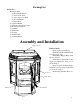
Packing List Inside Stove: Hardware Pack (2) Electrical Terminals (1) 10-32 x 1/2" Bolt (1) 1/4 x 20 x 2 1/2" Bolt (1) Wooden Handle (1) Brass Knob (1) Owners Manual (1) Warranty Activation Coupon (1) Room Sensing Probe (1) Ash Pan (2) Firebricks (1) Scraper (1) Flame Guide (1) Cleaning Brush Assembly and Installation Hopper Knob Final Assembly Remove parts from ash pan. Install Wooden Door Handle with 1/4 x 20 x 2 1/2 bolt. Install Brass Hopper Knob with 10-32 x 1/2 bolt.
Installing Place the stove on a noncombustible floor protector and away from combustible walls at least as far as shown in figure 2 and 3. Note that the clearances shown are minimum for safety but do not leave much room for access when cleaning or servicing. Please take this into account when placing the stove. Place the Room Sensing Probe in the desired location and run standard thermostat wire back to the terminals on the back of the stove and connect with the two terminals provided.
Venting A combustion blower is used to extract the combustion gases from the firebox. This causes a negative pressure in the firebox and a positive pressure in the venting system as shown in fig. 4. The longer the vent pipe and more elbows used in the system, the greater the flow resistance. Because of these facts we recommend using as few elbows as possible and 15 feet or less of vent pipe.
#1 Preferred method This method provides excellent venting for normal operation and allows the stove to be installed closest to the wall. Two inches from the wall is safe, however, four inches allows better access to remove the rear panel. The vertical portion of the vent should be three to five feet high. This vertical section will provide natural draft in the event of a power failure. 3 ft. to combustibles Fig.
#4 Installing into an existing chimney ( US only ) This method provides excellent venting for normal operation. This method also provides natural draft in the event of a power failure. If the chimney condition is questionable you may want to install a liner as in method #7. Fig. 7 #5 Installing into an existing fireplace chimney ( US only ) This method provides excellent venting for normal operation. This method also provides natural draft in the event of a power failure.
#6 Installing into an existing fireplace chimney ( US and Canada ) This method provides excellent venting for normal operation. This method also provides natural draft in the event of a power failure. In Canada and some places in the US it is required that the vent pipe extend all the way to the top of the chimney. In this method a cap should also be installed on the chimney to keep out rain. Be sure to use approved pellet vent pipe fittings.
DO NOT INSTALL A FLUE DAMPER IN THE EXHAUST VENTING SYSTEM OF THIS UNIT. WARNING DO NOT INSTALL IN SLEEPING ROOM DO NOT CONNECT THIS UNIT TO A CHIMNEY FLUE SERVING ANOTHER APPLIANCE. CAUTION INSTALL VENT AT CLEARANCES SPECIFIED BY THE MANUFACTURER THE STRUCTURAL INTEGRITY OF THE MOBILE HOME FLOOR, WALL, AND CEILING/ROOF MUST BE MAINTAINED. Mobile home installation should be done in accordance with the Manufactured Home and Safety Standard (HUD), CFR 3280, Part 24.
Operation Starting First Fire Be sure the power cord is plugged into a 120 volt receptacle. This can be verified by the red power light on the control panel. Fill the hopper with pellets, fig. 12. Fill the burn pot with pellets to a level just short of overflowing, fig. 8. Fig. 8 Adjust feed rate. If this is your first fire or you are trying different pellets, set the feed adjuster to "3", fig. 9. This is a conservative number and will probably need to be increased.
Scrape floor of burn pot with scraper to remove any carbon build-up before starting a new fire. Starting a fire after proper Feed Rate is known. Clean burn pot with scraper (supplied). Fill the hopper with pellets. Fill the burn pot with pellets to a level just short of overflowing. Fig. 11 When filling hopper be sure to remove any pellets from ledge and around hinges before closing lid. Adjust feed rate to proper setting. After you know what feed rate works well, then use that setting.
Fig. 13 When to use "Stove Temp Mode" In "Stove Temp Mode" the Stove Temp Dial determines the temperature of the stove. Heat output and fuel consumption will remain constant. This makes it possible to tell how long a hopper full of pellets will last. The distribution blower speed will vary according to the position of the mode selector, fig. 13. When to use "Room Temp Mode" This setting will produce medium heat with the distribution blower on "low".
ESP CONTROL Power Light Indicates power to the control. Secondary function: Blinks every 15 seconds when the feed adjuster is in "Test Mode". This verifies feeder switch operation. Should be lit anytime the unit is pluged in. Feed adjuster Sets the maximum feed rate Test Runs all motors at full speed for two minutes to check operation. After two minutes the stove will go to minimum burn and the blowers will alternate from high to low every two minutes to remind you that you are still in "Test Mode".