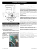
Installation & Operating Manual The Harman PP38+ Pellet Stove “Ce manuel est disponible en Français sur demande” SAFETY NOTICE Please read this entire manual before you install and use your new room heater. Failure to follow instructions may result in property damage, bodily injury, or even death. FOR USE IN THE U.S. AND CANADA. SUITABLE FOR INSTALLATION IN MOBILE HOMES. IF THIS HARMAN STOVE IS NOT PROPERLY INSTALLED, A HOUSE FIRE MAY RESULT. FOR YOUR SAFETY, FOLLOW INSTALLATION DIRECTIONS.
3-90-08422R27_09/12 An outside combustion air inlet must be provided. Refer to Manufacturer’s instructions and local codes regarding the requirements for passing the exhaust venting system through a combustible wall or ceiling. WARNING : THE STRUCTURAL INTEGRITY OF THE MANUFACTURED HOME FLOOR, WALL, AND CEILING/ROOF MUST BE MAINTAINED. DO NOT INSTALL IN SLEEPING ROOM. DO NOT REMOVE THIS LABEL / NE PAS ENLEVER CETTE ÉTIQUETTE Keep Viewing and Ash Removal Doors Tightly Closed During Operation.
Introduction WARNING Table of Contents Safety Information 5 do not connect to any air distribution duct or system. Installation 6 Venting 8 ESP Control 15 Operation 16 WARNING do not use chemicals or fluids to start the fire. do not burn garbage or flammable fluids such as gasoline, naptha, or oil.
IMPORTANT NOTES DO NOT INSTALL A FLUE DAMPER IN THE EXHAUST VENTING SYSTEM OF THIS UNIT. DO NOT CONNECT THIS UNIT TO A CHIMNEY FLUE SERVING ANOTHER APPLIANCE. SPECIAL NOTE: Due to fly ash buildup, it is strongly recommended that you have your stove professionally cleaned and serviced annually. This includes all parts of the stove, and the entire venting system. CAUTION WARNING M o b i l e / M a n u fa c t u r e d H o m e Standards Do Not Allow Installation In Rooms Designated For Sleeping.
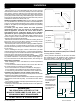
Assembly and Installation Route Room Sensor cable through here. Fig. 1 Shipping Bolts Note: These same holes are used for securing the stove in mobile home installation. Rear Cover Panels Optional Room Sensor Installation The optional room sensor (part #3-20-00906) is a small temperature sensor on the end of a 60" wire. This sensor is installed much like a standard wall thermostat. There is a remote room sensor port on the rear of the unit for easy external connection.
Installation Mobile Home Installation When installing this unit in a mobile home, several requirements must be followed: 1. The unit must be bolted to the floor. This can be done with 1/4" lag screws through the 2 holes in the base plate. 2. The unit must also be connected to outside air. See page 9. 3. Floor protection and clearances must be followed as shown. 4. Unit must be grounded to the metal frame of the mobile home. CAUTION: This appliance must be vented to the outside.
Venting Requirements for Terminating the Venting WARNING: Venting terminals must not be recessed into a wall or siding. NOTE: Only approved pellet vent pipe, wall passthroughs, and fire stops should be used when venting through combustible materials. NOTE: Always take into consideration the effects of the prevailing wind direction or other wind currents that may cause flyash and/or smoke when placing the termination of the vent. In addition, the following must be observed: A.
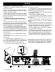
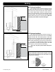
Venting IMPORTANT NOTICE Approved 3" or 4" Pellet Vent Pipe Such As, Type "PL", Must Be Used. Fig. 7 + - = Positive Static Pressure = Negative Static Pressure + Vent Pipe Pellet venting pipe (known as PL vent) is constructed of two layers with air space between the layers. This air space acts as an insulator and reduces the outside surface temperature to allow a clearance to combustibles of 1 to 3 inches. The sections of pipe lock together to form an air tight seal in most cases.
Venting Outside air flex pipe goes here. Per national building codes, consideration must be given to combustion air supply to all combustion appliances. Failure to supply adequate combustion air for all appliance demands, may lead to back-drafting of those and other appliances. When the appliance is side-wall vented: The air intake is best located on the same exterior wall as the exhaust vent outlet and located lower on the wall than the exhaust vent outlet.
Venting #1 Preferred method 3 ft. to Combustibles Fig. 8 This method provides excellent venting for normal operation and allows the stove to be installed closest to the wall. Two inches from the wall is safe; however, four inches allows better access to remove the rear panel. The vertical portion of the vent should be three to five feet high. This vertical section will help provide natural draft in the event of a power failure. Note: Do not place joints within wall pass-throughs. 3 ft.
Venting #4 Installing into an existing chimney This method provides excellent venting for normal operation. This method also provides natural draft in the event of a power failure. If the chimney condition is questionable* you may want to install a liner as in method #7. In some places in the US and Canada it is required that the vent pipe extend all the way to the top of the chimney. *The chimney should be inspected and cleaned before installing your stove.
Venting #6 Installing into an existing fireplace chimney This method provides excellent venting for normal operation. This method also provides natural draft in the event of a power failure. In some places in the US and Canada it is required that the vent pipe extend all the way to the top of the chimney. The pipe or liner inside the chimney should be 4" diameter. In this method a cap should also be installed on the chimney to keep out rain. Be sure to use approved pellet vent pipe fittings.
Venting 12" min. Storm collar Flashing 3" min. 3" min. PL vent manufacturer's firestop spacer and support 3" min. No insulation or other combustible materials are allowed within 3" of the pellet vent pipe. Unless specified by the pipe manufacturer Minimum flue vent configuration It is required that outside air be installed with this venting configuration to reduce smoke and creosote smell in the room in the event of power failure. 3" min. Fig. 14 18" #8 Installing through the ceiling Min.
ESP CONTROL Power Light Indicates power to the control. Feed adjuster Sets the maximum feed rate Status Light Will be lit in either stove or room temp mode when pointer is not within off position band except after normal shut down. Blinks to indicate errors listed below. Test Runs all motors at full speed for one minute to check operation. Afterwards, the control will simulate a minimum burn and the combustion blower will remain on low for draft test convenience.
OPERATION The PP38+ features two operating modes; Stove Temperature Mode and Room Temperature Mode. In Stove Temperature Mode, you select a burn rate and the stove will remain at the same burn rate regardless of the room temperature. In the Room Temperature Mode, with the optional room sensor attached, the stove constantly monitors the temperature in the room and adjusts the size of the fire and the heat output of the stove so that the room is kept at a constant temperature.
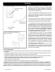
OPERATION Stove Temperature Mode In the Stove Temperature Mode, the stove can be adjusted to the desired setting using the same temperature control dial as is used in the Room Temperature Mode. The heat output and fuel consumption will remain constant regardless of room temperature. The settings from 1 to 7 on the inner ring of the temperature dial provide for relative heat output settings with 1 being low and 7 being the maximum. Never pull the plug to shut down the stove.
OPERATION Starting First Fire Make sure the unit is plugged into a 120 VAC, 60 HZ electrical source. The power light should be the only light lit. Fig. 17 Flame Guide See Hint #7. 1" Notice: Be sure there is no unburned fuel or other combustibles in the ash pan prior to lighting. 1. Turn FEED ADJUSTER to desired feed rate. No. 4 is good for most pellets.4 Fig. 18 Helpful Hints 1. Fines are small pieces of broken pellets (sawdust).
Draft Test Procedure A simple draft test should be performed before and after completing the flue pipe installation. To compare and to record the results for future reference: 1. Plug the unit into a 120 VAC, 60 HZ outlet. 2. Close the hopper lid, front view door, and the ash pan. Neither pellets or a fire are required for this test. 3. With the mode selector in the "OFF" position, turn the feed adjuster to "TEST". 4. Record the high draft______in W.C. (Normal is -.50 to -.
Maintenance Minimizing Creosote: Whenever wood is burned slowly, the potential exists for creosote to form in the venting. The chimney or venting system should be inspected periodically throughout the heating season to determine if a creosote buildup has occurred. If a significant layer of creosote has accumulated (3mm or more), it should be removed to reduce the risk of a chimney fire.
Maintenance Scraping the burn pot: Whenever adding fuel to the hopper, take the time and scrape the grate surface of the burnpot, using the scraper tool provided. This can be done while a fire is burning. Wearing heat resistant gloves, open the firebox door. Scrape any accumulated ashes from in front of the fire, into the ash pan. Now, scrape under the fire, in a downward direction, to loosen any carbon deposits. Do not scrape the fire out of the pot.
Maintenance 6. Remove the ash pan and properly dispose of the ashes. 7. Remove combustion blower cover by turning the blower cover latch vertical, see Fig.26. Sliding the cover out of the slot on the left. This will expose the combustion blower wheel and flue outlet, Fig.27. Burn pot Clean-out plate Fig. 28 Latch "closed "with blower cover in place. Burn pot clean-out is closed. Fig. 29 Latch "open "with blower cover partly removed. Burn pot clean-out is open. 8.
Maintenance - Burn Pot Burn Pot Cleaning and Maintenance 1. Scrape the top holed surface and sides of the burn pot. (Fig 33) It is not necessary to completely remove all material from the burn pot. The excess will be pushed out during the next use. DANGER Disconnect the power to the unit before removing cover. Loosen wing screws Fig. 34 2. Loosen the (2) wing thumb screws on the lower front angle of the burn pot. (Fig. 34) 3. Lift off the clean-out cover (Fig.35) to open the bottom clean-out chamber.
Maintenance - Cleaning the Feeder Body Pellet fines may accumulate in the feeder body over a period of time; therefore, a yearly inspection and cleaning of this area must be performed. To clean out fines: 1. Remove the rear cover panels. 2. Remove wing nut and feeder cover on the side of the feeder. 3. Use a vacuum cleaner to remove all fines. 4. Reinstall feed cover, wing nut, and rear cover panels.
Trouble-Shooting STOVE DOES NOT FEED 1. No fuel in hopper. 2. Firebox draft may be too low for sensing switch in feeder circuit to operate. Check for closed doors, loose or missing gasket on doors or hopper lid. 3. Hopper lid must contact the lid position switch. 4. Feed motor will not run until the ESP control senses a certain temperature. Maybe you did not put enough fuel or starting gel in the burn pot before manually lighting the fire. 5. Restriction in the hopper or feeder. Remove all fuel and examine.
Specifications 10" 13.625" 32.375" 22" Weight 212 lbs. Blower 135 cfm Feed Rate approximate .75lb. to 5.5 lbs per hr Hopper Capacity 50 lbs Fuel Wood Pellets Flue Size 3 inch Outside Air Size 2 3/8" I.D. inch Fuse Rating 6 amp 28.5" 5.
Options Side Heat Shields -Part #1-00-773863 Direct Vent Wall Passthrough Kit Side heat shields are available to reduce the clearance to combustible materials. You may choose to use the optional Direct Vent Wall Passthrough Kit (part #1-00-677077) which incorporates venting passthrough and outside air into one component.
Addendum for Burning Corn and Pellet Fuel Mixture Harman pellet burning, free-standing stoves and inserts have been tested to ASTM E1509 for burning shelled corn in a mixture with wood pellets. The listing approves up to a 50% corn and 50% pellet mixture. Different mixtures of corn will have distinctively different burn characteristics depending upon moisture content and variety.
Fuel Specifications Fuel and Fuel Storage Pellet fuel quality can fluctuate from manufacturer to manufacturer, and even from bag to bag. Hearth & Home Technologies recommends using only fuel that is certified by the Pellet Fuels Institute (PFI).
CORD LOW PRESSURE SWITCH N.O. CONTACTS WHITE BROWN REV FEEDER AUGER MOTOR REVISIONS MALE/FEMALE CONNECTIONS N.O. CONTACTS HOPPER LID SWITCH 3-20-232108 ESP ESP CONTROL BOARD DATE 1 11 8 9 10 3 4 5 6 BY --MATL PN TITLE -- -- -- SPARE NUMBER PART NUMBER DRAWN BY -- -- -- USED ON FINISH WEIGHT or LENGTH MATERIAL PART NO.
Hearth & Home Technologies Inc. LIMITED LIFETIME WARRANTY Hearth & Home Technologies Inc., on behalf of its hearth brands (”HHT”), extends the following warranty for HHT gas, wood, pellet, coal and electric hearth appliances that are purchased from an HHT authorized dealer.
WARRANTY CONDITIONS: • • • • This warranty only covers HHT appliances that are purchased through an HHT authorized dealer or distributor. A list of HHT authorized dealers is available on the HHT branded websites. This warranty is only valid while the HHT appliance remains at the site of original installation. Contact your installing dealer for warranty service. If the installing dealer is unable to provide necessary parts, contact the nearest HHT authorized dealer or supplier.
P38 Pellet service Parts steel Pellet stove beginning Manufacturing date: n/a ending Manufacturing date: active 1-90-08500-1 (black), retired units 1-70-08500-1 (black) (ending Manufacturing date: May 2006) 1-90-08500-2 (charcoal) (ending Manufacturing date: june 2011) 1-90-08500-3 (goldenfire) (ending Manufacturing date: june 2011) 1-90-08500-4 (Metallic blue) (ending Manufacturing date: jan 2010) 1 1-90-08500-5 (honey glo) (ending Manufacturing date: june 2009) 1-90-08500-10 (Mojave red) (ending Man
P38 Pellet service Parts beginning Manufacturing date: n/a ending Manufacturing date: active IMPORTANT: THIS IS DATED INFORMATION. When requesting service or replacement parts for your appliance please provide model number and serial number. All parts listed in this manual may be ordered from an authorized dealer.
P38 Pellet service Parts beginning Manufacturing date: n/a ending Manufacturing date: active #2 Pre serial number 00808066 Feeder assembly 2.3 2.2 2.1 2.4 2.5 2.6 2.12 2.7 2.11 2.8 2.9 2.10 IMPORTANT: THIS IS DATED INFORMATION. When requesting service or replacement parts for your appliance please provide model number and serial number. All parts listed in this manual may be ordered from an authorized dealer.
P38 Pellet service Parts beginning Manufacturing date: n/a ending Manufacturing date: active #3 Post serial number 008280066 Feeder assembly 3.1 3.12 3.15 3.16 3.14 3.2 3.13 3.11 3.3 3.10 3.9 3.4 3.5 3.8 3.7 3.6 IMPORTANT: THIS IS DATED INFORMATION. When requesting service or replacement parts for your appliance please provide model number and serial number. All parts listed in this manual may be ordered from an authorized dealer.
P38 Pellet service Parts beginning Manufacturing date: n/a ending Manufacturing date: active IMPORTANT: THIS IS DATED INFORMATION. When requesting service or replacement parts for your appliance please provide model number and serial number. All parts listed in this manual may be ordered from an authorized dealer.
Service & Maintenance Log Date Of Service 37 PP38+ Pellet Stove Performed By Description Of Service 3-90-08422R27_09/12
At Harman, we build each product to a standard, not a price. This powerful heating appliance boasts uncompromising attention to detail and helps preserve our planet by using environmentally responsible fuels. (Signature of Boxer) Your premium quality hearth product designed and assembled by the experienced and skilled members at Harman in Halifax, PA, USA.